Advertisement
Quick Links
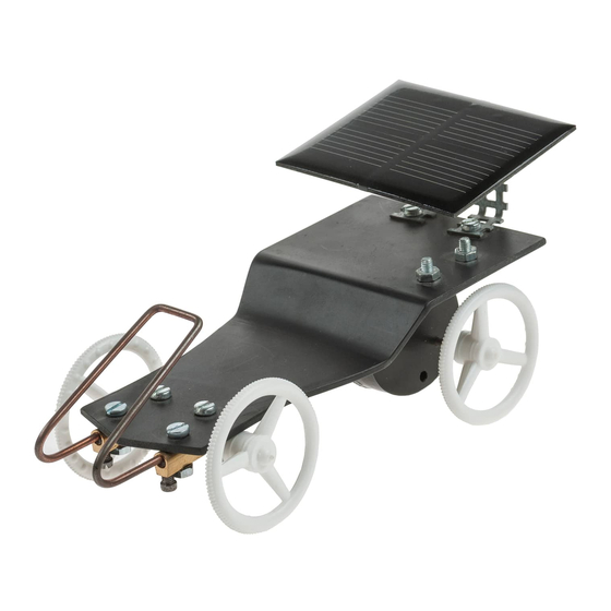
S o l a r A u t o w i t h g e a r b o x
The OPITEC range of projects is not intended as play
toys for young children.They are teaching aids for young
people learning the skills of Craft, Design and Technolo-
gy.These projects should only be undertaken and tested
with the guidance of a fully qualified adult.
The finished projects are not suitable to give to children
under 3 years old. Some parts can be swallowed. Dan-
PART LIST
Polystyrol
Holed metal strip
Welding rod
Motor & gearbox
Steering wheels
Solar cell
Machine screws
Machine screws
Machine screws
Solarmotor
Nuts
Connecter block
Reducers
E109793#1
Please Note
ger of suffocation!
1
2
1
1
4
1
2
8
2
1
10
2
4
109.793
Necessary tools:
Pencil,ruler,
Fretsaw,sandpaper and block
File,Drill ø 3 mm
Plastc former
Screwdriver, Side cutters (Metal shears ),
Spanner 5,5
Pliers, Round nose pliers
Description
130x60x2 Base chassis
150x10x0,5 Fixing
200x2 Axle & bumper
Drive
ø37 Wheels
Electricity source
10x3 Fixings
8x3 Fixing Drive/Axle/Solar cell
6x3 Fixing bumper/connector block
Drive
M3 Fixing
Fixing bumper
3/2 Fitting Axle and wheels
1
2
3
4
5
6
7
8
9
10
11
12
13
1
Advertisement

Related Manuals for Opitec Solar Auto with gearbox


Summary of Contents for Opitec Solar Auto with gearbox
- Page 1 S o l a r A u t o w i t h g e a r b o x Necessary tools: Please Note Pencil,ruler, The OPITEC range of projects is not intended as play Fretsaw,sandpaper and block toys for young children.They are teaching aids for young File,Drill ø 3 mm...
- Page 2 INSTRUCTIONS 1. Mark out on the chassis (1) the holes ( See page 5 for patterns ) Drill the 3mm diameter holes and cut out the shape with a Fretsaw. File the sawn deges to finish . General : The base chassis (1) can be folded or left flat. The instructions show how to fold the chassis. 2.
- Page 3 INSTRUCTIONS 5. From the square holed metal strip (2) cut two lengths each 9 holes long and bend them as shown in the pattern on page (5) Mount the metal strips as shown (e) using a machine screw (8) and a nut (11) see abb. (f ) Abb.
- Page 4 INSTRUCTIONS 9. Screw the connector block (12) as shown in Abb. (k) to the Abb. k underside of the chassis with the machine screws (7) and nuts (11) tighten. 10.Insert the wire rod bumper in the connector block and screw Abb.
- Page 5 INSTRUCTIONS Chassis plan M 1:1 Bending patterrn for the chassis Scale 1:1 Bending pattern M1:1 Right angle for fixing the motor Axle holder Solar axle holder Bend here Pattern for the bumper M1:1 E109793#1...
Need help?
Do you have a question about the Solar Auto with gearbox and is the answer not in the manual?
Questions and answers