Table of Contents
Advertisement
Quick Links
Advertisement
Table of Contents

Subscribe to Our Youtube Channel
Related Manuals for Huvema HU 45 INDUSTRY


Summary of Contents for Huvema HU 45 INDUSTRY
- Page 1 C O L U M N D R I L L I N G M A C H I N E HU 45 INDUSTRY...
-
Page 2: Table Of Contents
able of conTenTs General safety rules for all machines Additional safety rules Conditions of use Characteristics Description of the machine Structure Sound level and installation Table tilting Table adjustment Setting the speed V belt tension Feed shaft spring tension Setting the drilling depth Inserting and ejecting the drill and chuck 4.10 Positioning a work piece Maintenance... -
Page 3: General Safety Rules For All Machines
hu 45 i olumn drilling machine ndusTry 1. g eneral safeTy rules for all machines N.B.: Read the instructions carefully in order to avoid any problems. As with all machinery there are certain hazards involved with operation and use of this machine. Using the machine with respect and caution will considerably lessen the possibility op personal injury. -
Page 4: Additional Safety Rules
ddiTional safeTy rules Always keep in mind that: • The machine must be switched off and disconnected from the power supply during maintenance and repairs, • Clamped workpieces may only be measured when the machine is switched off. Never lean over the machine, mind loose clothing, ties, jewellery etc. And wear a cap. Do not remove safety devices or guards. -
Page 5: Description Of The Machine
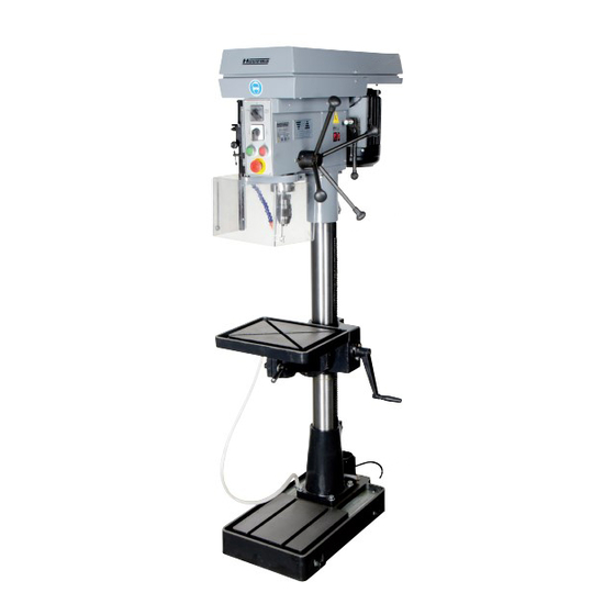
4. d escripTion of The machine 4.1 s TrucTure Figure 1 Head Column and rack and pinion Table and bracket Base plate with column support 4.2 s ound level and insTallaTion Max. noise level while working: 80 db (A) These values are measured under normal use of the machine. Incorrect use of the machine can produce different values! Always wear hearing protection for maximum safety while working. -
Page 6: Setting The Speed
4.3 T able TilTing Unlock the lever under the table and tilt the table to the desired position using the graduated scale. Lock the handle again. Figure 2 4.4 T able adjusTmenT • Vertical: to adjust the table vertically you must first loosen the clamp lever and then set the height using the lever A, figure 3. -
Page 7: Feed Shaft Spring Tension
4.7 f eed shafT spring Tension The feed shaft return spring is set at the factory; however, during the life of the drill press you may want to adjust the spring so that the feed shaft return pressure suits your operating needs. Turn the machine off and disconnect it from the mains before maintenance or repairs are performed! Figure 5 •... -
Page 8: Inserting And Ejecting The Drill And Chuck
4.9 i nserTing and ejecTing The drill and chuck Figure 7 Figure 9 Figure 8 • Insert the chuck into the spindle (figure 7). • Place the drill in the chuck (figure 8) and turn the drill. The chuck is self-centering. •... -
Page 9: Description Of The Electric Parts
6.2 d escripTion of The elecTric parTs The main elements of the electric system are: • Main panel MG45R-14.1-0 • Push buttons panel MG40-14.2A-0 • Panel MG45R-14.3-0 • Safety switch SQ3 for the v belt protection cover • Main motor M1 •... -
Page 10: Electric Scheme
7. e lecTric scheme Figure 10 CHANGES AND T YPING ERRORS RESER VED... -
Page 11: Wiring Diagram
7.1 w iring diagram Figure 11 Positive switch (v belt cover) Anti-positive switch (drill cover) Change pole switch (SA2) CHANGES AND T YPING ERRORS RESER VED... -
Page 12: Electric Elements
8. e lecTric elemenTs Figure 12 CHANGES AND T YPING ERRORS RESER VED... -
Page 13: Troubleshooting
9. T roubleshooTing Problem Possible cause Possible solution Too much noise Wrong belt tension Adjust tension Spindle not lubricated Remove spindle quill and lubricate Pulley loose Tighten pulley V-belt loose Adjust belt tension Worn bearing Exchange bearing Play of the chuck Drill chuck loose Tighten by pressing chuck against table Worn spindle shaft or bearing... -
Page 14: Parts Drawing
10. p arTs drawing 73 74 69 70 82 83 163-2 163-1 162-1 161-1 161 163-3 163-4 168-1 170-1 171-1 185-2 185-1 171-2 185-3 171-3 24 23 22 Figure 13 CHANGES AND T YPING ERRORS RESER VED... - Page 15 All rights reserved. No part of this booklet may be reproduced in any form, by print, photoprint, microfilm or any other means without written permission from the publisher. © Huvema BV, Kennedylaan 14, Veghel, the Netherlands. Internet: www.huvema.nl CHANGES AND T YPING ERRORS RESER VED...
Need help?
Do you have a question about the HU 45 INDUSTRY and is the answer not in the manual?
Questions and answers