Table of Contents
Advertisement
Quick Links
Advertisement
Table of Contents

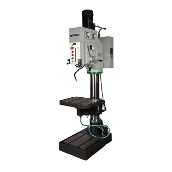
Summary of Contents for Huvema HU 40 TI
- Page 1 D R I L L I N G M A C H I N E S HU 40 TI HU 40 TI...
- Page 2 CHANGES AND T YPING ERRORS RESER VED...
- Page 3 CHANGES AND T YPING ERRORS RESER VED...
- Page 4 CHANGES AND T YPING ERRORS RESER VED...
- Page 5 CHANGES AND T YPING ERRORS RESER VED...
- Page 6 CHANGES AND T YPING ERRORS RESER VED...
- Page 7 CHANGES AND T YPING ERRORS RESER VED...
- Page 8 CHANGES AND T YPING ERRORS RESER VED...
- Page 9 CHANGES AND T YPING ERRORS RESER VED...
-
Page 10: Table Of Contents
able of conTenTs General safety rules for all machines Attention 2.1. Safety 2.2. Caution Machine appearance, applications and work environment 3.1. Machine appearance 3.2. Applications 3.3. Work environment Technical specifications Transportation and installation 5.1. Transport of the machine 5.2. Foundation and installation Transmission 6.1. -
Page 11: General Safety Rules For All Machines
40 Ti olumn drilling machine eneral safeTy rules for all machines N.B.: Read the instructions carefully in order to avoid any problems. As with all machinery there are certain hazards involved with operation and use of this machine. Using the machine with respect and caution will considerably lessen the possibility op personal injury. -
Page 12: Attention
Please read the operation manual carefully before the installation and adjustment of the machine. When the installation is finished, check all components and perform an idle trial run before putting the machine into operation. In case of problems, please contact your Huvema dealer. 2.2. c auTion Make sure you read all the safety instructions and follow them carefully. -
Page 13: Technical Specifications
echnical specificaTions Description Measure Unit Maximal drilling diameter Distance between axis of spindle – column surface Max. distance between spindle nose and work table surface Max. distance between spindle nose and base surface 1200 Max. spindle travel Max. travel of work table and bracket Horizontal swing of table on bracket ±... -
Page 14: Foundation And Installation
5.2. f oundaTion and insTallaTion Figure B – Foundation dimensions • Take the work table as radius, go 360° around the column to determine the max. area of the foundation. The diameter of the foundation is 1800 mm (see figure B). Customers can decide the foundation area according to their own needs. -
Page 15: Operation Instructions
peraTion insTrucTions 7.1. s TarTing The machine • Before starting the machine, read carefully the operation manual and become fully acquainted with all the details. • The operator should be familiar with all the rules and points of attention for running and maintaining the machine. -
Page 16: Spindle Reset
7.5. s pindle reseT The balance and reset of the spindle are accomplished by the coiled spring. The force of spindle balance can be adjusted by loosening the screw and turning the angle of the spring housing. 7.6. T ool loading and unloading See figure A 7.6.1. -
Page 17: Hand Oiling
8.1.2. h and oiling • Hand lubricating places (see figure F) • Hand lubricating method (see table 3) Place of Description Method Lubricant Cycle lubrication Main driving shaft I bearing Oil gun Lithium grease no. 3 Every 3 months Main driving shaft II bearing Oil gun Lithium grease no. -
Page 18: Electrical Circuit
10.2. e lecTrical circuiT Picture I Picture J – control circuit J1 – Drilling/tapping J2 – Raising/lowering J3 – Indicator of power J4 – Feed clutch 10.2.1. m (Qs1) ain power swiTch The main power switch (QS1) is for controlling the power supply. It has opening for safety locking with a padlock. 10.2.2. -
Page 19: Maintenance Of Electrical Equipment
10.4. m ainTenance of elecTrical eQuipmenT Disconnect the main power supply before checking the electrical equipment. Keep the equipment clean by removing dust, dirt and grease regularly. You may not use volatile liquids (such as kerosene or gasoline) as cleaner. The working voltage of the motor must not exceed 5 % of the rated voltage. To ensure the machine runs normally, regular maintenance of the motor is a must. -
Page 20: Construction Of Main Components
N.25 screw N.25 Deep groo 螺钉 深沟球轴承 N.26 Washer N.26 Circlip 垫片 卡环 N.27 work table N.27 washer 工作台 垫圈 N.28 screw N.28 Screw 螺杆 螺钉 12. c N.29 Stopper N.29 washer onsTrucTion of main componenTs 挡块 垫圈 N.30 Handle N.30 Bearing 手柄杆... - Page 21 ZX5040 PAGE2 - PAGE 3 Picture O - 3D drawing of spindle box and gear system 序号 名称 N.47 Knurled knob sleeve N.47 Deep groove ball bearings 滚花把手 套 深沟球轴承 N.48 Worm shaft N.48 Washer Scale rolling head 蜗杆轴 垫圈 标尺扎头...
- Page 22 N.98 Small handle bars N.149 Gear 小手柄杆 齿轮 N.99 Spindle Box N.150 Gear 主轴箱体 齿轮 N.151 Washer N.100 Positioning sleeve 垫圈 定位套 N.152 Bearing N.101 Worm shaft 轴承 蜗轮轴 N.153 Bearing cover N.102 Bearing 轴承盖 轴承 N.154 Bearing cover 轴承盖 N.103 Washer 垫圈...
- Page 23 CHANGES AND T YPING ERRORS RESER VED...
- Page 24 All rights reserved. No part of this booklet may be reproduced in any form, by print, photoprint, microfilm or any other means without written permission from the publisher. Huberts bv, Kennedylaan 14, Veghel, the Netherlands. Internet: www.huvema.nl CHANGES AND T YPING ERRORS RESER VED...
-
Page 25: Ce Declaration Of Conformity
(in accordance with supplement II A of the Machinery Directive) Industrie & Handelsonderneming Huberts bv, Kennedylaan 14, 5466 AA Veghel, the Netherlands, in the capacity of importer, is to be held responsible for declaring that the Huvema machine: Column drilling machine HU 40 TI... - Page 26 CHANGES AND T YPING ERRORS RESER VED...
- Page 27 CHANGES AND T YPING ERRORS RESER VED...


Need help?
Do you have a question about the HU 40 TI and is the answer not in the manual?
Questions and answers