Table of Contents
Advertisement
Quick Links
Advertisement
Table of Contents

Subscribe to Our Youtube Channel
Related Manuals for Huvema HU 20 SUPER


Summary of Contents for Huvema HU 20 SUPER
- Page 1 D R I L L I N G M A C H I N E S HU 20 SUPER HU 20F SUPER...
-
Page 2: Table Of Contents
able of conTenTs General safety rules for all machines Additional safety rules Unpacking Transportation instruction Features Installing the machine Main parts Control panel T-grooves Work table adjustment 7.2.1 Height adjustment 7.2.2 Angle adjustment 7.2.3 Turning Drill depth adjustment Speed Selection V belt adjustment Noise levels Troubleshooting... -
Page 3: General Safety Rules For All Machines
hU 20 s - hU 20f s rilling machines Uper Uper 1. g eneral safeTy rUles for all machines N.B.: Read the instructions carefully in order to avoid any problems. As with all machinery there are certain hazards involved with operation and use of this machine. Using the machine with respect and caution will considerably lessen the possibility op personal injury. -
Page 4: Additional Safety Rules
2. a DDiTional safeTy rUles Always keep in mind that: • the machine must be switched off and disconnected from the power supply during maintenance and repairs, • clamped workpieces may only be measured when the machine is switched off. Never lean over the machine, mind loose clothing, ties, jewellery etc. -
Page 5: Features
(or flatportion of the arbor shown in Figure 21) fitsinto. eaTUres 5.Seat the chuck with a rubber mallet, as shownin Figure 22. Model HU 20 Super HU 20F Super Drilling capacity 20 mm 20 mm... -
Page 6: Main Parts
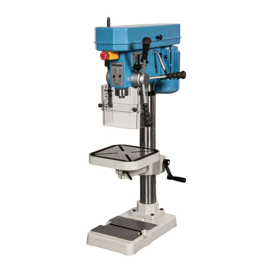
The dimension of setting hole: JTD-19S JTD-19SF HU 20 Super HU 20F Super Figure 4 6. m ain parTs Pulley cover Motor Emergency stop Handle v belt tension Head Feed handle Drill head Column Chuck guard Rack Table Table height... -
Page 7: Control Panel
C.Emergency Stop Button (For CE) 7. c onTrol panel A. Jkm Cam Switch (high/low) A: Speed selection switch B: Start button C: Emergency stop B.Start Button(For CE) C.Emergency Stop Button (For CE) 1. Check the power source Push the start button to judge the motor and spindle shaft is in normal condition or not. -
Page 8: Drill Depth Adjustment
4. Adjustment of feeding limit 7.3 D To prevent unwanted penetration to work piece, the feeding limit rill DepTh aDjUsTmenT shall be set by adjusting the appropriate position of feeding depth To prevent the drill from going too deep into the work piece, you can set the fixing button as long as the distance between the end of tool and feeding limit by adjusting the position of the feed depth knob top surface if work piece is measured. -
Page 9: Noise Levels
For proper belt tension, you should be able to push the belt in to a distance of about 13 mm. Machine model Belt specifications Quantity Models belt model tables Machine model JTD-16S A-42 Belt specifications Quantity HU 20 Super JTD-16SA A-25 / A-26 FM-42.5 Machine model Belt specifications Quantity HU 20F Super FM-42.5 JTD-19 FM-42.5... -
Page 10: Feed Shaft Spring Tension
• Engage the next available spring cover lock slot and push the spring lock cover back. • Retighten the lock nut and replace the cover. 10. D imensions Dimensions(m/m) All dimensions in mm. JTD-19S JTD-19SF HU 20 Super HU 20F Super 1050 1730 C C=470 × c1=280 C=500 × c1=330 D=280 × d1=280 1280 ... -
Page 11: Control Circuit Diagram
7.Control circuit diagram and component part list; 11. c onTrol circUiT Diagram Figure 17 Symbol Function Tech. dat Remark Motor AC400V / 3PH Part No. Component/Object Manufacturer Relay AC400V 7.5A LY-3 Motor AC400V / 3PH / Limit switch 400V / 5A RELAY AC 400V7.5A LY-3... -
Page 12: Parts Drawing And List
8.Drawing and parts list; JTD-19S 12. p arTs DraWing anD lisT HU 20F Super JTD-19SF Figure 18 CHANGES AND T YPING ERRORS RESER VED CHANGES AND T YPING ERRORS RESER VED... - Page 13 FEED HANDLE MICRO SWITCH BRACKET JTD-19 series 101A MICRO SWITCH GRIP 101B MICROSWITCH BOARD COVER SCALE RING BASE 101C MICRO SWITCH WIRE SCALE COLUMN HOLDER 101-S1 SCREW RIVET 2-S1 BOLT 101-S2 SCREW SPRING CAP 101-S3 LEAD BOLT 2-S2 SPRING WASHER SAFETY GUARD COLUMN QUILL...
- Page 14 All rights reserved. No part of this booklet may be reproduced in any form, by print, photoprint, microfilm or any other means without written permission from the publisher. © Huberts bv, Kennedylaan 14, Veghel, the Netherlands. Internet: www.huvema.nl CHANGES AND T YPING ERRORS RESER VED CHANGES AND T YPING ERRORS RESER VED...
-
Page 15: Ce Declaration Of Conformity
(in accordance with supplement II, section 1A of the Machinery Directive) Industrie & Handelsonderneming Huberts bv, Kennedylaan 14, 5466 AA Veghel, the Netherlands, in the capacity of importer, is to be held responsible for declaring that the Huvema machines: Drilling machines HU 20 Super - hU 20f Super...
Need help?
Do you have a question about the HU 20 SUPER and is the answer not in the manual?
Questions and answers