Table of Contents
Advertisement
Quick Links
Advertisement
Table of Contents

Subscribe to Our Youtube Channel
Related Manuals for Huvema HU 40 GTF Super Vario


Summary of Contents for Huvema HU 40 GTF Super Vario
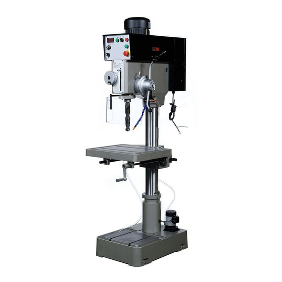
- Page 1 C O L U M N D R I L L I N G M A C H I N E HU 40 GTF Super Vario...
- Page 2 Safety Guidelines Keep the work area clear. Remove foreign objects prior to operation so as to ensure safety. Use the safety guard. The safety guard prevents Chips from spraying out and causing cuts or burns. Remove adjusting keys and wrenches before turning machine on. ...
-
Page 3: Table Of Contents
Parts list D – Electric box....................... 22 Explosion Drawing E – Control Panel ................... 23 9.10 Parts List E – Control Panel ....................24 9.11 Parts List – Electrical Components for HU 40 GTF Super Vario .......... 25 9.12 Electrical Drawing – Wiring Diagram ..................26... -
Page 4: Specifications
Thank you for purchasing HU 40 GTF Super Vario Variable Speed Drilling Machine. Please read this manual carefully before operating the machine and keep the operating manual for later reference. This machine is of fine quality and stable performance. It is equipped with drilling and tapping functions and can be operated for years given regular maintenance and proper usage. -
Page 5: Description Of Machine
1 Description of Machine... -
Page 6: Transporting The Machine
Transporting the Machine When transporting in its original own packaging, please use a forklift truck or hand trolley. Find the proper position to place machine then anchor it. 3 Getting to Know Your Machine Control Panel ON Switch – Starts the motor. Stop Switch –... -
Page 7: The Machine Base
The Machine Base The Machine base houses the coolant tank and pump. The coolant tank is a reservoir to hold coolant. The coolant pump transfers coolant up to the machine head and onto the drill bit. Coolant is a solution that lowers tool wear and enhances drilling by cooling and lubricating the drilling tool. -
Page 8: Minimum Requirement For Housing The Machine
Minimum Requirement for Housing the Machine Please comply with the following terms to maximize the life and performance of the machine and its components. The Main voltage and frequency complying with the requirements for the machine’s motor. Environment temperature from –10°C to +50°C. Relative humidity not over 90%. -
Page 9: Machine Operation
5 Machine Operation Changing the Spindle Speed Change speed ranges using lever (Fig. J) only while the machine is stopped. Failure to do so can cause damage to the gear system. Then spindle speed can be adjusted to the proper drilling RPM by using the spindle speed knob (F, Fig.1). -
Page 10: Automatic Down-Feed
Automatic down-feed Automatic down-feed is feature for use only while drilling. The down-feed rate changes can only be made while machine is running and is in drilling mode. Rate of the automatic spindle down-feed (Fig. 8) is equal to A: 0.2, B: 0.05, and C: 0.1. -
Page 11: The Operation Cycle
The Operation Cycle Check that the head is secure. Warning! Failure to lock the head handles can result in damage of the machine and personal injury. Secure the work piece to the table. Adjust the table to the desired height. Use the front or side crankshaft. -
Page 12: Adjusting The Machine
6 Adjusting the machine Removing the Tools from Spindle Bore Disconnect machine from power supply. Place a thin wood plank on the worktable to protect the surface of the worktable. Raise the worktable to about 250mm under the bit. Lower the spindle about 150mm. Place the drift key (Q, Fig.10) into the aperture (R, Fig. -
Page 13: Cleaning And Accessing The Coolant System
Cleaning and Accessing the coolant system Cleaning is required when iron filings clog the screen (B,Fig.6) at the bottom right corner of the water drain entry at the base. Fig.6 Uncover the base plate (P, Fig.11). Loosen the screw (D, Fig.11) to remove the plate and the fixed pump on it. -
Page 14: Daily Maintenance
Daily Maintenance Make a general cleaning by removing dust and shavings from the machine. Check that the shields and emergency stops are in good working order. After daily use, disconnect machine from power source or press emergency stop switch to shut off the power completely. -
Page 15: Table Of Error Codes For The Inverter
Table of Error Codes for the Inverter Code Error description Solution * The voltage inverter detects the * Check if voltage of the motor matches with output current exceeds the normal that of the voltage inverter. value. * Check connection between the voltage inverter &... -
Page 16: Drawings And Parts Lists
9 Drawings And Parts Lists Explosion Drawing A – Motor/pulley assembly... -
Page 17: Parts List A - Motor/Pulley Assembly
Parts List A – Motor/pulley assembly NO. Description Size Q’TY NO. Description Size Q’TY B-01 Hex Hand Plugs 3/8" B-40 Tube B-02 Sight Glass B-41 Oil Seal 62x35x10 B-03 Ball Bearing 6202ZZ B-42 C-Clip R-47 B-04 C-Clip S-31 B-43 Oil Seal 47x25x8 B-05 Gear... -
Page 18: Explosion Drawing B - Head/Spindle Assembly
Explosion Drawing B – Head/Spindle assembly... -
Page 19: Parts List B - Head/Spindle Assembly
Parts List B – Head/Spindle assembly Description Size Q’ty Description Size Q’ty Flat Head Screw M6x16 A-49 Hex Socket Cap Screw M6x16 A-02 Cover A-50 Allen Wrench A-03 Feed Clutch Rod A-51 Lock Nut A-04 A-52 Star Washer A-05 Roll Pin A-53 Taper Roller Bearing 30206... - Page 20 Description Size Q’ty Description Size Q’ty A-95 Spring M6x8 A-140 3x10 A-96 Steel Ball A-141 Drive Spindle Pulley M=8,T=64 A-97 Spring Pin A-142 Rear Spindle Pulley M=5,T=38 A-98 Speed Change Support A-143 Pulley Guard A-99 Speed Change Pin A-144 Safety Washer A-100 Screw M4x6...
-
Page 21: Explosion Drawing C - Column/Table/Base
Explosion Drawing C – Column/Table/Base... -
Page 22: Parts List C - Column/Table/Base
Parts List C – Column/Table/Base Description Size Q'ty Description Size Q'ty C-01 Coolant Base C-33 Spring Pin 4x25 C-34 Crank Shaft C-02 Spring Pin 4x50 C-35 Ball Bearing 6005Z C-03 Hex Head Plugs 3/8" C-36 Bevel Gear C-04 Set Screw 1/2"x1"... -
Page 23: Explosion Drawing D - Electric Box
Explosion Drawing D – Electric box... -
Page 24: Parts List D - Electric Box
Parts list D – Electric box Description Size Q'ty E-01 Electric Control Box w/Door and Latch E-02 Plastic Plate E-03 Screw M4x6 E-04 Cover E-05 Electric Base Plate E-06 Cable Relief E-07 Washer E-08 Hex Socket Cap Screw M8x12 E-09 Electric Cable E-10 Delta Inverter (for 460V) -
Page 25: Explosion Drawing E - Control Panel
Explosion Drawing E – Control Panel... -
Page 26: Parts List E - Control Panel
9.10 Parts List E – Control Panel Description Size Q'ty D-01 Start Switch D-02 Stop Switch D-03 Emergency Stop Switch D-05 Pump Switch D-06 Speed Control Knob D-07 Speed Controller D-07A Holder Screw D-08 Screw D-10 Plate Bracket D-11 Washer D-12 Hex Socket Cap Screw M8x20... -
Page 27: Parts List - Electrical Components For Hu 40 Gtf Super Vario
9.11 Parts List – Electrical Components for HU 40 GTF Super Vario Description Item Technical Suppliers Quantity Supplier Remarks designation data reference function Ui690V Disconnecting KEDU 2H-C316 Device EN60947 IP54 600V Fuses 0.5A 30mm GIN SING 600V 3A Coil 24V... -
Page 28: Electrical Drawing - Wiring Diagram
9.12 Electrical Drawing – Wiring Diagram... - Page 29 All rights reserved. No part of this booklet may be reproduced in any form, by print, photoprint, microfilm or any other means without written permission from the publisher. © Huvema BV, Kennedylaan 14, Veghel, the Netherlands. Internet: www.huvema.nl CHANGES AND T YPING ERRORS RESER VED...
Need help?
Do you have a question about the HU 40 GTF Super Vario and is the answer not in the manual?
Questions and answers