Table of Contents
Advertisement
Quick Links
Advertisement
Table of Contents

Related Manuals for Huvema HU 45 DM Vario


Summary of Contents for Huvema HU 45 DM Vario
- Page 1 HU 45 DM Vario - Operation manual...
- Page 2 Safety Guidelines Keep the work area clear. Remove foreign objects prior to operation so as to ensure safety. Use the safety guard. The safety guard prevents Chips from spraying out and causing cuts or burns. Remove adjusting keys and wrenches before turning machine on. ...
-
Page 3: Table Of Contents
TABLE OF CONTENTS ..Machine specification ....................4 ..Specifications ..........................4 ..Machine Dimensions ........................4 ..Description of Machine ......................4 ..Transporting the Machine ..................5 ..Getting to Know Your Machine .................. 5 ..3.1. Control Panel ..........................5 .. - Page 4 Explosion Drawing A – Head / Motor / Electric Control ............17 ..9.1. Parts List A – Head / Motor / Electric Control ................18 ..9.2. Parts List A – Head / Motor / Electric Control (Contiuned) ............19 ..
-
Page 5: Machine Specification
Thank you for purchasing MD-930 Variable Speed Drilling and Milling Machine. Please read this manual carefully before operating the machine and keep the operating manual for later reference. This machine is of fine quality and stable performance. It is equipped with drilling、milling and tapping functions and can be operated for years given regular maintenance and proper usage. -
Page 6: Description Of Machine
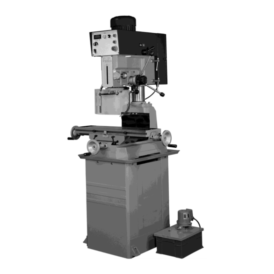
1.3 Description of Machine Motor Digital Tachometer Hi/Low gear Selector Control Panel Head Lock Levers Depth Scale Depth lock Micro-feed Hand Wheel Quill Feed Hand Quill Lock Levers Wheel Safe Guard Coolant Nozzle Cross Table Hand Wheel Hand Wheel Machine Stand Pump Coolant Tank... -
Page 7: Getting To Know Your Machine
2. Transporting the Machine When transporting in its original own packaging, please use a forklift truck or hand trolley. Find the proper position to place machine then anchor it. 3. Getting to Know Your Machine 3.1. Control Panel A. ON Switch – Starts the motor. B. -
Page 8: The Machine And Head
3.3. The Machine and Head The machine head can move up and down, and be rotated 360°. It allows more flexibility in work piece sizes. Turn off machine. Unlock the head handles (I–Fig. 2). Use the riser handle (H, Fig.2.1) to raise or lower the head. -
Page 9: Warning Marking
3.6. The Machine table and base The machine base consists of a cross table and base assembly. The machine base is used to hold the work piece. The table is able to move forward and backwards, left and right for adjusting and milling the work piece. -
Page 10: Minimum Requirement For Housing The Machine
Initial Cleaning Machine is shipped with a rustproof oil coating. Clean the rustproof oil coating from all exposed metal surface. Then apply oil/grease. 4.2. Minimum Requirement for Housing the Machine Please comply with the following terms to maximize the life and performance of the machine and its components. -
Page 11: Electrical Connection Of The Machine
4.5. Electrical Connection of the Machine Make sure whether the voltage of the acquired machine is 220V/1 phase or (220V, 380V, 400V,440V)/3 phases prior to connection. If the machine cannot be operated after wires have been connected, please check the following items: The Emergency switch is released. -
Page 12: Setting The Depth And Stop
5.2. Setting the Depth and Stop Set the depth to zero by lowering the cutting tools to the surface of the work piece. Lock the quill position by using either the quill lock handle (N–fig. 5) or the depth handle lock knob (L–fig. -
Page 13: Operation Cycle
5.5. The Machine table and base The table is able to move forward and backwards, left and right for adjusting and milling the work piece. Lock both tables when drilling. Lock the table of the non- milling axis when milling. The work table is T-slotted to allow the use of M14 or ½”... -
Page 14: In Drilling Mode
Unlock the table, use the table lock levers (K–fig. 6). Use the table hand wheels to begin milling. Lower the quill, use the micro-feed hand wheel (O–fig. 5) and lock it by using the quill lock handle (N–fig. 5). Any further depth adjustment requires the unlocking of the quill before using the micro-feed hand wheel(O–fig. -
Page 15: Adjusting The Machine
Adjusting the Machine Removing the Tools from Spindle Bore 6.1. Disconnect machine from power supply. Place a thin wood plank on the worktable to protect the surface of the worktable. Raise the worktable to about 250mm under the bit. Lower the spindle about 150mm and lock by using the quill lock (N–fig.5) or the depth lock knob (L–fig.6.1). -
Page 16: Lubrication And Routine Maintenance
guard. Loosen knob (X-Fig.11) to open the safety chuck guard, when it opened that the power will be shut off. Adjusting the table slack 6.5. The machine is equipped with gib strip Z1 (Fig.13) adjustment to compensate for wear and excess slack on cross-table. -
Page 17: Weekly Maintenance
After daily use, disconnect machine from power source or press emergency stop switch to shut off the power completely. Do not keep the machine connected over 24 hours, it may cause damage to the machine. Weekly Maintenance 7.3. Inspect if the screen is clogged by iron, thoroughly clean the machine including the coolant tank by referring to 6.2. -
Page 18: Table Of Error Codes For The Inverter
Table of Error Codes for the inverter 8.2. Code Error description Solution * The voltage inverter detects the * Check if voltage of the motor matches with output current exceeds the normal that of the voltage inverter. value. * Check connection between the voltage inverter &... -
Page 19: Drawing And Parts Lists
Drawing and Parts Lists Explosion Drawing A – Head / Motor / Electric Control 9.1. -
Page 20: Parts List A - Head / Motor / Electric Control
Parts List A – Head / Motor / Electric Control 9.2. Description Size Q'TY NO. Description Size Q'TY Head body 6x20 Oil window S-30 Washer Ball bearing 6202z Hex socket cap screw M8x25 C-Clip S-31 Emergency stop switch Gear M=2,T=32 Stop switch 6x20 Start switch... -
Page 21: Parts List A - Head / Motor / Electric Control (Contiuned)
Parts List A – Head / Motor / Electric Control (Contiuned) 9.3. NO. Description Size Q'TY NO. Description Size Q'TY 134 C-Clip R-47 95 Cross head screw M3x16 96 Micro switch 135 Hex socket cap screw M8x12 136 Washer 97 Micro switch bracket 98 Micro switch support rod 137 Bearing support 99 Sensor bracket... -
Page 22: Explosion Drawing B - Head / Spindle Assembly
Explosion Drawing B – Head / Spindle Assembly 9.4. -
Page 23: Explosion List B - Head / Spindle Assembly
Explosion List B – Head / Spindle Assembly 9.5. NO. Description Size Q'TY NO. Description Size Q'TY Head body 53 Face plate Head body hex. Bolt 58 Screw 3/16"x5/16" Bushing 60 Depth scale bracket Handle 61 Set screw 3/16"x1/2" Set screw 5/16"x3/4"... -
Page 24: Explosion Drawing C - Column / Table / Base
Explosion Drawing C – Column / Table / Base 9.6. -
Page 25: Explosion List C - Column / Table / Base
Explosion List C – Column / Table / Base 9.7. NO. Description Size Q'TY NO. Description Size Q'TY 1-1 Base 43-1 Middle base Lifting hook Leaf screw Holder ring Moveable fixed block Screw 3/16"x5/16" Jib strip bolt Cover plate 47-1 Lock handle Screw 3/16"x5/16"... -
Page 26: Stand-Explosion Drawing & Parts List
STAND-Explosion Drawing & Parts List 9.8. -
Page 27: Coolant System-Explosion Drawing & Parts List
Coolant System-Explosion Drawing & Parts List 9.9. -
Page 28: Electrical Components & Wiring Diagram
Electrical Components & Wiring Diagram Parts List- Electrical Components for MD-930-1 10.1. Item Description and Technical Suppliers Quantity Supplier Remarks designation function data reference Ui690V IP65 Disconnecting MOELLER TO 2/1V CE UL Device IP54 IEC947-3 FU1,2 600V32A CT-10Mam10A Fuses FU3,4 250V 0.5A Conquer UFE-F1AL250V... -
Page 29: Parts List- Electrical Components For Md-930-3
Parts List- Electrical Components for MD-930-3 10.2. Item Description and Technical Suppliers Quantity Supplier Remarks designation function data reference Ui690V IP65 Disconnecting MOELLER TO 2/1V CE UL Device IP54 IEC947-3 FU1,2,3 600V32A CT-10Mam10A Fuses FU4,5 250V 0.5A Conquer UFE-F1AL250V UL CSA 250V 3A Conquer UTE-T2AL250V... -
Page 30: Electrical Drawing - Wiring Diagram For Md-930-1
Electrical Drawing – Wiring Diagram for MD-930-1 10.3. - Page 31 (in accordance with supplement II, section 1A of the Machinery Directive) Industrie & Handelsonderneming Huberts bv, Kennedylaan 14, 5466 AA Veghel, the Netherlands, in the capacity of importer, is to be held responsible for declaring that the Huvema machine: 12009 HU 45 DM Vario...
Need help?
Do you have a question about the HU 45 DM Vario and is the answer not in the manual?
Questions and answers