Table of Contents
Advertisement
Quick Links
A986 OWNER'S MANUAL CONTENTS
1. INTRODUCTION ................................................................................ 2
2. SAFETY PRECAUTIONS ..................................................................
3. LIST OF PARTS .................................................................................
4. ASSEMBLE THE PRODUCT .............................................................
STEP 1 Install the Seat Base .................................................................
STEP 2 Install the Central Support .......................................................
STEP 3 Install the Arm Assemblies .......................................................
STEP 4 Install the Cushion Adjustment Assembly ................................
STEP 5 Install the Seat Bottom Cushion ............................................... 10
STEP 6 Install the Weight Plate Pegs ................................................... 11
STEP 7 Level the Unit ........................................................................... 12
STEP 8 Operate the Product ................................................................. 13
5. MAINTENANCE ................................................................................ 14
MAINTENANCE Schedule .................................................................... 14
MAINTENANCE Task List .................................................................... 15
MAINTENANCE One-Year Maintenance Log ....................................... 16
7. CONSIGNES DE SÉCURITÉ IMPORTANTES ................................. 17
3
4
6
6
7
8
9
Advertisement
Table of Contents

Related Manuals for SportsArt Fitness A986


Summary of Contents for SportsArt Fitness A986
-
Page 1: Table Of Contents
A986 OWNER’S MANUAL CONTENTS 1. INTRODUCTION ................2 2. SAFETY PRECAUTIONS ..............3. LIST OF PARTS ................. 4. ASSEMBLE THE PRODUCT ............. STEP 1 Install the Seat Base ..............STEP 2 Install the Central Support ............STEP 3 Install the Arm Assemblies ............ -
Page 2: Introduction
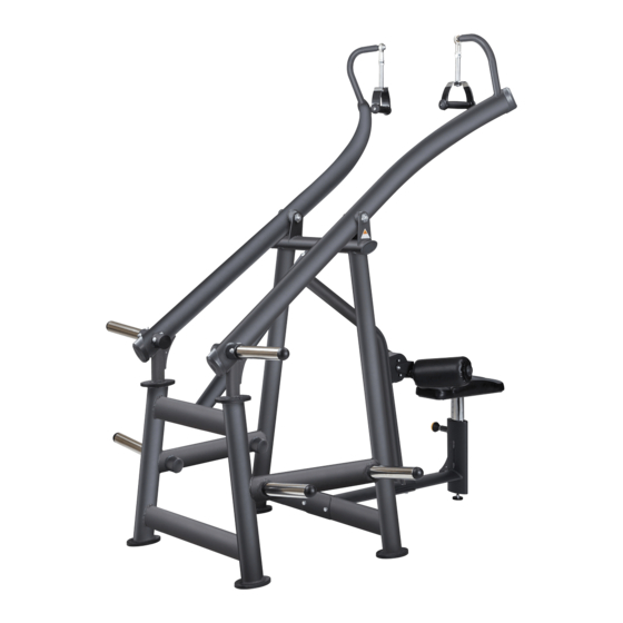
1. INTRODUCTION Congratulations on the purchase of a high quality SportsArt product, the A986 lat pulldown machine. Constructed of high quality materials and designed for years of reliable performance, this product was made for full commercial use. Before this product is assembled or operated, we recommend that you familiarize yourself with this manual. -
Page 3: Safety Precautions
2. SAFETY PRECAUTIONS This product was designed and built for optimum safety. However certain precau- tions apply during the use of this product. Please note the following safety precautions: • Please read the entire manual before assembly and operation. Make sure the product is installed and operated as instructed in this manual. -
Page 4: List Of Parts
3. LIST OF PARTS Assembly Parts No. Name Qty. No. Name Qty. A1 Main frame A6 Seat bottom cushion A2 Left arm assembly A7 Seat base A3 Right arm assembly A8 Connector A4 Central support A9 Weight plate peg Cushion adjustment assembly... - Page 5 Components on the Product Name Specification Notes Hex screw M10*P1.5*L75 Spring washer Washer D16*d10.2*t1.0 Bushing D16*t2*L45.5 Lock nut Inner hex screw M8*L20 Mushroom top inner hex screw M8*P1.25*L20 Spring washer Flat washer D26*d8.3*t3 Bushing Axle D25*L104 double M8 Mushroom top inner hex screw M8*L25 Mushroom top inner hex screw M6*P1.0*L15...
-
Page 6: Assemble The Product
4. ASSEMBLE THE PRODUCT Follow instructions below to assemble this product. Note that in this manual the words “left” and “right” are used to refer to the product and its parts. As such, these designations correspond to the “left” and “right” sides of a person in position to exercise on this product. -
Page 7: Step 2 Install The Central Support
STEP 2 Install the Central Support Please follow instructions below to secure the central support into place. First, remove the connector plate (A8) from the mainframe (A1) and the seat base (A7). Align the holes in the top of the central support (A4) with those in the seat base (A7) and connect with connector plate (A8). -
Page 8: Step 3 Install The Arm Assemblies
STEP 3 Install Arm Assemblies Please follow instructions (a) through (b) below to install left and right arm assemblies. (a) First, remove screws (30) from the main frame (A1). (b) Align the left arm (A2) to the holes in the main frame (A1). Then use screws (30) to secure the assembly. -
Page 9: Step 4 Install The Cushion Adjustment Assembly
STEP 4 Install the Cushion Adjustment Assembly Please follow instructions (a) through (b) to install the cushion adjustment assembly. (a) Remove the screw assembly (31) in the central support (A4). (b) Insert the bushing from the screw assembly (31) into the central support (A4). -
Page 10: Step 5 Install The Seat Bottom Cushion
STEP 5 Install the Seat Bottom Cushion Please follow instructions (a) through (d) to install the seat bottom cushion into place. (a) First, remove screws (32) from the seat bottom cushion (A6). (b) Then remove the lock screws (34) from the seat base (A7). (c) This will free a metal plate from the seat bottom cushion (A6). -
Page 11: Step 6 Install The Weight Plate Pegs
STEP 6 Install Weight Plate Pegs Please follow instructions (a) through (c) to install weight plate pegs into place. (a) First, remove screws (33) from the weight plate pegs (A9). (b) Then loosen the screws (35) on both arm assemblies (A2,A3) on the both sides of the main frame (A1). -
Page 12: Step 7 Level The Unit
STEP 7 Level the Unit Please follow instructions (a) through (c) to level the unit. (a). Loosen leveler nuts. (b). Rotate the leveler feet downward to the floor. (c). Rotate the nuts upward, against the product, to secure this position. -
Page 13: Step 8 Operate The Product
STEP 8 Operate the Product Please follow instructions (a) through (d) to operate the product. (a) Select the appropriate weight plates placed on both sides of the weight plates pegs, and then secure the weight plates with safety clamps. (b)Adjust the seat height and the cylindrical cushion position, so the thighs are fixed under the cusion. -
Page 14: Maintenance
5. MAINTENANCE This section covers maintenance topics and includes a maintenance sched- ule, task list, and log. MAINTENANCE Schedule Area Week Month Quarter Year Notes Exterior Clean. Screws Inspect for looseness and secure if necessary. Cushions Wipe with a damp cloth. Extension rod Clean and lubricate. -
Page 15: Maintenance Task List
MAINTENANCE Task List Like cars, fitness products require maintenance. Regular maintenance ex- tends product life, and failure to maintain products can void the manufac- turer’s warranty. Copy the maintenance log sheet, and record maintenance work for each fitness product. Daily tasks 1. -
Page 16: Maintenance One-Year Maintenance Log
MAINTENANCE One-Year Maintenance Log Facility:_______________________ Supervisor:____________________ Product model number:__________ Serial number:_________________ Start date: ____________________ End date:_____________________ Daily Tasks Weeks 1-7 Weeks 8-14 Weeks 15-21 Week 22-28 Completed Daily Tasks Week 29-35 Week 36-42 Week 43-49 Week 50-52 Completed Weekly Tasks Weeks 1-7 Weeks 8-14 Weeks 15-21 Weeks 22-28... -
Page 17: Consignes De Sécurité Importantes
6. CONSIGNES DE SÉCURITÉ IMPORTANTES Le produit SportsArt a été conçu et fabriqué afin d’assurer une sécurité optimale. Cependant certaines précautions s’appliquent chaque fois que vous utilisez votre produit. • Lisez entièrement le manuel avant l’assemblage et l’utilisation. Veuillez aussi noter les consignes de sécurité... - Page 18 • Ce produit n’est pas destiné à être utilisé par des personnes (y compris des enfants) dont les capacités physiques, sensorielles ou mentales sont réduites ou qui ne disposent pas de l’expérience ou du savoir nécessaires, sauf si celles-ci ont au préalable été formées eu égard à l’utilisation de ce produit par une per- sonne responsable de leur sécurité.
Need help?
Do you have a question about the A986 and is the answer not in the manual?
Questions and answers