Table of Contents
Advertisement
Quick Links
A985 OWNER'S MANUAL CONTENTS
1. INTRODUCTION ................................................................................ 2
2. SAFETY PRECAUTIONS ..................................................................
3. LIST OF PARTS .................................................................................
4. ASSEMBLE THE PRODUCT .............................................................
STEP 1 Install the Seat Frame ...............................................................
STEP 2 Install the Seat Back Support ................................................... 7
STEP 3 Install the Support Frame ......................................................... 8
STEP 4 Install the Seat Cushion ........................................................... 9
STEP 5 Install the Arm Assemblies ....................................................... 10
STEP 6 Install the Weight Plate Pegs ................................................... 11
STEP 7 Install the Level the Unit .......................................................... 12
5. OPERATE THE PRODUCT ............................................................... 13
OPERATION Operate the Product ........................................................ 13
6. MAINTENANCE ................................................................................ 14
MAINTENANCE Schedule .................................................................... 14
MAINTENANCE Task List .................................................................... 15
MAINTENANCE One-Year Maintenance Log ....................................... 16
7. CONSIGNES DE SÉCURITÉ IMPORTANTES ................................. 17
3
4
6
6
Advertisement
Table of Contents

Subscribe to Our Youtube Channel
Related Manuals for SportsArt Fitness A985


Summary of Contents for SportsArt Fitness A985
-
Page 1: Table Of Contents
A985 OWNER’S MANUAL CONTENTS 1. INTRODUCTION ................2 2. SAFETY PRECAUTIONS ..............3. LIST OF PARTS ................. 4. ASSEMBLE THE PRODUCT ............. STEP 1 Install the Seat Frame ............... STEP 2 Install the Seat Back Support ........... 7 STEP 3 Install the Support Frame ............8 STEP 4 Install the Seat Cushion ............ -
Page 2: Introduction
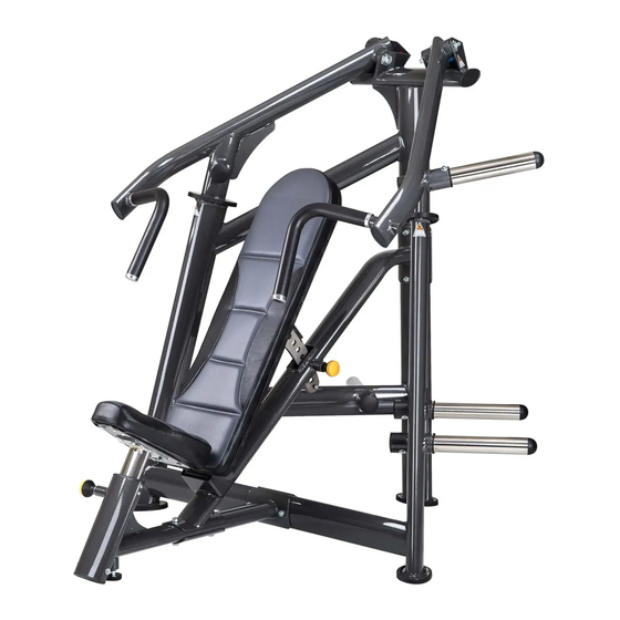
1. INTRODUCTION Congratulations on the purchase of a high quality SportsArt product, the A985 chest press machine. Constructed of high quality materials and designed for years of reliable performance, this product was made for full commercial use. Before this product is assembled or operated, we recommend that you familiarize yourself with this manual. -
Page 3: Safety Precautions
2. SAFETY PRECAUTIONS This product was designed and built for optimum safety. However certain precau- tions apply during the use of this product. Please note the following safety precautions: • Please read the entire manual before assembly and operation. Make sure the product is installed and operated as instructed in this manual. -
Page 4: List Of Parts
3. LIST OF PARTS Assembly Parts No. Name Qty. No. Name Qty. A1 Main frame A6 99 oval connecting plate A2 Support frame A7 Right arm assembly A3 Seat frame A8 Left arm assembly A4 Seat cushion A9 Seat back support A5 118 oval connecting plate 1 A10 Weight plate peg... - Page 5 Components in the Hardware Kit Name Qty. Specification Notes L-shaped Allen wrench L-shaped Allen wrench Double open-end wrench 13*17 Open-end wrench Components on the Product Name Specification Notes Inner hex screw M10*P1.5*L75 Spring washer Washer D16*d10.2*t1.0 Bushing ØD16*t2*L45.5 Hex nylon nut Mushroom top inner hex screw M8*P1.25*L25 Beveled head inner hex screw...
-
Page 6: Assemble The Product
4. ASSEMBLE THE PRODUCT Follow instructions below to assemble this product. Note that in this manual the words “left” and “right” are used to refer to the product and its parts. As such, these designations correspond to the “left” and “right” sides of a person in position to exercise on this product. -
Page 7: Step 2 Install The Seat Back Support
STEP 2 Install the Seat Back Support (a) First, remove screws (25) from the seat back support (A9). (b) Attach the seat back support (A9) onto the support frame (A2), then se- cure the assembly with screws (25). -
Page 8: Step 3 Install The Support Frame
STEP 3 Install the Support Frame (a) First, remove the connecting plates (A5) and (A6) from the main fram (A1) and the seat frame (A3). (b) Then, position the support frame (A2) to the main frame (A1) and the seat frame (A3) where the screw holes align. -
Page 9: Step 4 Install The Seat Cushion
STEP 4 Install the Seat Cushion Please follow instructions (a) through (c) to install the seat cushion. (a) First remove the screws (21) from the seat cushion assembly (A4), and also remove screws (24) from the seat frame (A3). (b) Place the seat cushion plate onto the seat frame (A3), and secure the assembly with screws (24). -
Page 10: Step 5 Install The Arm Assemblies
STEP 5 Install the Arm Assemblies Please follow instructions (a) through (b) to install the arm assembly. (a) First, remove the screws (22) from the main frame (A1). (b) Attach the right arm assembly (A7) onto the main frame (A1), secure the assembly with screws (22). -
Page 11: Step 6 Install The Weight Plate Pegs
STEP 6 Install the Weight Plate Pegs Please follow instructions (a) through (c) to install weight plate pegs. (a) First remove the screws (23) from the weight plate pegs (A10). (b) Then loosen screws (27) from both arm assemblies. Install weight plate pegs (A10) onto both arm assemblies (A7)(A8) and the sides of the main frame (A1). -
Page 12: Step 7 Install The Level The Unit
STEP 7 Level the Unit If the unit is not flat on the ground, please follow instructions below to adjust the level adjustment knob. (a) Lossen the level adjustment knob and rotate downward until it touches the ground. (b) Determine the level adjustment knob position and the tighten up the nut to secure the position. -
Page 13: Operate The Product
5. OPERATE THE PRODUCT OPERATION Operate the Product (a) Select the appropriate weight plates placed on both sides of the weight plate pegs, and then secure the weight plates with safety clamps. (b) Adjust the seat height and back support to the most comfortable position. (c) Select the horizontal grip or vertical grip. -
Page 14: Maintenance
6. MAINTENANCE This section covers maintenance topics and includes a maintenance sched- ule, task list, and log. MAINTENANCE Schedule Area Week Month Quarter Year Notes Exterior Clean. Screws Inspect for looseness and secure if necessary. Cushions Wipe with a damp cloth. Seat tube Clean and lubricate once every six months. -
Page 15: Maintenance Task List
MAINTENANCE Task List Like cars, fitness products require maintenance. Regular maintenance ex- tends product life, and failure to maintain products can void the manufac- turer’s warranty. Copy the maintenance log sheet, and record maintenance work for each fitness product. Daily tasks 1. -
Page 16: Maintenance One-Year Maintenance Log
MAINTENANCE One-Year Maintenance Log Facility:_______________________ Supervisor:____________________ Product model number:__________ Serial number:_________________ Start date: ____________________ End date:_____________________ Daily Tasks Weeks 1-7 Weeks 8-14 Weeks 15-21 Week 22-28 Completed Daily Tasks Week 29-35 Week 36-42 Week 43-49 Week 50-52 Completed Weekly Tasks Weeks 1-7 Weeks 8-14 Weeks 15-21 Weeks 22-28... -
Page 17: Consignes De Sécurité Importantes
7. CONSIGNES DE SÉCURITÉ IMPORTANTES Le produit SportsArt a été conçu et fabriqué afin d’assurer une sécurité optimale. Cepen- dant certaines précautions s’appliquent chaque fois que vous utilisez votre produit. • Lisez entièrement le manuel avant l’assemblage et l’utilisation. Veuillez aussi noter les consignes de sécurité...
Need help?
Do you have a question about the A985 and is the answer not in the manual?
Questions and answers