Sign In
Upload
Manuals
Brands
Covidien Manuals
Medical Equipment
Newport e360
Covidien Newport e360 Manuals
Manuals and User Guides for Covidien Newport e360. We have
1
Covidien Newport e360 manual available for free PDF download: Service Manual
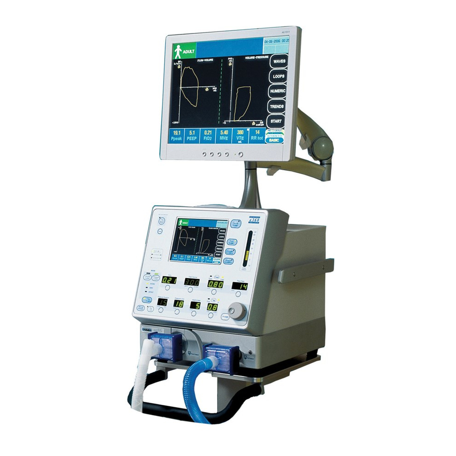
Covidien Newport e360 Service Manual (154 pages)
Ventilator with Accessories
Brand:
Covidien
| Category:
Medical Equipment
| Size: 27.88 MB
Table of Contents
Table of Contents
3
Definitions
13
Other Definitions
13
General Warnings
14
General Cautions
15
General Note
15
Service Guidelines
15
Overview
13
Warnings, Cautions, and Notes
13
Regular Service
15
Complete Service Records
16
Service Life
16
Disclaimers
16
Electromagnetic Compatibility (EMC)
16
Table 1-1. Electromagnetic Emissions
17
Table 1-2. Electromagnetic Immunity
17
Revision History
19
Warranty Information
19
Table 1-3. List of Compliant Cables
19
Contact Information
20
Maintenance, Overhaul, and Software Upgrade
25
General Warnings
25
Maintenance and Overhaul Intervals
25
Overview
25
General Cautions
26
Tools Required
26
Figure 2-2. Exhalation Valve Adapter
27
Parts Required
27
Preventive Maintenance Kit
27
Table 2-1. Preventive Maintenance Kit Parts List
27
Biannual Maintenance
28
Table 2-2. Overhaul Kit Parts List
28
Table 2-3. Parts Changed During Biannual Maintenance
28
Maintenance Procedures
29
Overhaul Kit
28
Figure 2-1. Inlet Water Trap Filter Replacement
29
Inlet Water Trap Filters and O-Ring Assembly
29
Exhalation Valve Adapter
30
Figure 2-3. Exhalation Valve Adapter Replacement
31
Exhalation Valve Diaphragm, Seal, and O-Ring
32
Figure 2-4. Diaphragm, Seal, and O-Ring Replacement
32
Emergency Relief Diaphragm
33
Figure 2-5. Inhalation Outlet Assembly
33
Figure 2-6. Emergency Relief Diaphragm Replacement
34
In-Line Disk Filters and Restrictor with Filter
34
Coin Battery (SBC2100P and SBC2108P)
35
Figure 2-8. J1 with CBL2132A Connected
35
Figure 2-9. Verifying the Time and Date
36
Cooling Fan Filter and Guard
37
Figure 2-10. Filter and Guard Assembly Replacement
37
Figure 2-11
38
Inhalation Outlet Check Valve
38
Overhaul Procedures
38
Inlet Water Trap Filter and O-Ring Assembly
38
Air and Oxygen Inlet Regulator Rebuild
39
Figure 2-12. Inlet Regulator Rebuild
39
Cooling Fan Filter and Guard
40
Emergency Relief Diaphragm
40
Exhalation Valve Adapter
40
Exhalation Valve Diaphragm/Poppet Assembly
40
Emergency Intake Diaphragm
41
Figure 2-13. Emergency Intake Diaphragm and Valve Replacement
41
Coin Battery (SBC2100P and SBC2108P)
42
Coin Battery (SBC2105A)
42
Figure 2-14. Location of the SBC PCBA, Coin Battery, and Internal Battery
43
Figure 2-15. Removing the Coin Battery
44
Figure 2-16. Inserting a New Coin Battery
44
Figure 2-17. Resetting the Time and Date
45
Biannual Maintenance
46
In-Line Disk Filters and Restrictor with Filter
42
Inhalation Outlet Check Valve
42
2.9 Biannual Maintenance
46
Figure 2-18. Verifying the Time and Date
46
Internal Battery
46
Oxygen Sensor
46
2.10 Software Upgrade Procedure
47
General Information
47
Tubing
47
Upgrade Procedure
47
Upon Completion
47
Software Upgrade Procedure
47
Figure 2-19. Software Download / Diagnostics Mode Screen
48
Circuit Check Test and Diagnostic
49
Figure 2-20. Event History Log Screen
49
Figure 2-21. Back Panel of Ventilator
50
Figure 2-22. Patient Circuit Setup
51
Figure 2-23. Ventilation Standby Screen
52
Figure 2-24. Circuit Check Screen
52
Figure 2-25. Circuit Check Screen (Step 2)
53
Figure 2-26. Technical Screen
53
Figure 2-27
54
Troubleshooting
57
Overview
57
Table 3-1. Troubleshooting Guide
57
Troubleshooting Guide
57
Device Alert Messages
59
Table 3-2. Device Alert Messages
59
4.2 Key Components
61
4.1 Overview
61
3.3 Device Alert Messages
61
3.2 Troubleshooting Guide
61
Component Removal and Replacement
61
Overview
61
Key Components
61
Ordering
61
Removing
61
Preparation
61
Tools Required
61
4.3 Preparation
62
Valve (EXH2105A) and Flow Sensor (FLS2101P)
62
Figure 4-1. Exhalation Valve and Exhalation Flow Sensor
63
Exhalation Flow Sensor Cable (Outside) (GR-CBL2123P)
64
Top Cover (CVR2101M)
64
Figure 4-2. Top Cover
64
Front Panel Assembly
65
Figure 4-3. Front Panel Assembly
65
4.4 Tools Required
62
Exhalation Valve and Exhalation Flow Sensor
62
4.5 Exhalation Valve and Exhalation Flow Sensor
62
4.8 Main Board and Main Board Support
67
4.7 Front Panel Assembly
67
Main Board and Main Board Support
67
4.6 Top Cover (CVR2101M)
67
Main Board (GR-PCB2100A)
67
Main Board Support (CVR2103M)
68
Figure 4-5. Main Board Support (CVR2103M)
68
Display Board (GR-PCB2109A)
69
Figure 4-6. Display Board (GR-PCB2109A)
69
Figure 4-7. Touch Screen Board (PCB2105P) (PCB2105P-M for E360T Model)
70
4.11 Large LCD Cable and LCD Display
71
4.10 Touch Screen Interface Board (PCB2105P) (PCB2105P-M for E360T Model)
71
Large LCD Cable and LCD Display
71
Touch Screen Interface Board (PCB2105P) (PCB2105P-M for E360T Model)
71
4.9 Display Board (GR-PCB2109A)
71
Large LCD Cable (GR-CBL2155A)
71
LCD Display (10139301)
72
Front Panel Cover (CVR2104M)
73
Optical Encoder (GR-ENC1800P)
74
Alarm Leds (GR-CBL2137A and GR-CBL2138A)
74
Touch Screen (GR-PNL2105P)
75
Figure 4-10. Touch Screen Panel (GR-PNL2105P)
75
Pneumatics Panel Assembly and Components
76
Figure 4-11. Pneumatics Cover
76
Panel Assembly (SVO2101A)
76
Figure 4-12. Cover (CVR2115M) and Gasket (GKT2101M)
77
Figure 4-13. Pneumatics Panel
78
Air and Oxygen Inspiratory Flow Sensors (GR-FTD2100P and GR-FTD2101P)
79
Figure 4-14. Inspiratory Flow Sensors
79
Figure 4-15. Pneumatics Panel Assembly
80
Regulators, Inlet Blocks, and Flow Sensor Block
80
PSOL Valves (10113777)
81
Figure 4-16. PSOL and Nylon String
82
Regulator and Solenoid Assembly (GR-BKT2105A)
83
Figure 4-17. Regulator and Solenoid Assembly (GR-BKT2105A)
83
Figure 4-18
84
Main Flow Outlet Block (GR-BLK2108A)
84
Figure 4-19. Outlet Block (BLK2108M)
85
Figure 4-20
85
Oxygen Sensor (SEN2103P)
85
Figure 4-21. Inhalation Outlet Block and Mixing Block
86
Inhalation Outlet Block and Mixing Block Assembly
86
Analog Board (GR-PCB2110A)
87
Figure 4-22. Analog Board (GR-PCB2110A)
87
Figure 4-23. Heater Assembly (GR-HTR2100A)
89
Heater Assembly (GR-HTR2100A)
89
Exhalation Manifold
90
Figure 4-24. Location of Screws and Bumper
90
Figure 4-25. Removal of Exhalation Manifold
90
Exhalation Flow Sensor Board (GR-PCB2103P)
91
Figure 4-26. Exhalation Flow Sensor Board (GR-PCB2103P)
91
Battery (BAT2100A)
92
Figure 4-27. Battery (BAT2100A)
92
AC/DC Power Supply (PWR2100P)
93
Figure 4-28. AC/DC Power Supply (PWR2100P)
93
DC to DC Power Supply (GR-PCB2101A)
94
Figure 4-29. DC to DC Power Supply (GR-PCB2101A)
94
Figure 4-30
95
Single-Board Computer (SBC2105A)
95
Power Sequence Board (GR-PCB2107A)
96
Calibration Procedures
97
Calibration Equipment
97
Overview
97
Figure 5-1. Newport™ E360 Ventilator Connected to Gas Sources
98
Setup
98
Diagnostic Mode
99
Analog PCB Calibration: D5
100
Procedures
100
Figure 5-2. Analog PCB
101
Table 5-2. Zero Offset Calibration
102
Table 5-3. Gain Calibration
103
Pneumatics Calibration
105
Figure 5-3. Air/Oxygen Pressure Regulators Adjustment
107
Table 5-4. Air Flow and Pressure Settings
107
Table 5-5. Oxygen Flow and Pressure Settings
107
Figure 5-4. Exhalation Psol/Safety Regulator
108
Operational Verification
113
Overview
113
Test Equipment
113
Figure 6-1. Test Setup
114
Setup
114
Current Leakage Test
115
Operational Checks
116
Table 6-1. Standard Test Settings
116
Electrical Safety Checks
115
Ground Resistance Test
115
Figure 6-2. Front Panel Controls and Indicators
117
Front Panel LED Check
117
Circuit Leak Test
118
Figure 6-3. Circuit Leak Test
118
Fio2 Test
119
Loss of Gas Alarm
119
Main Flow
120
Bias Flow
121
Inspiratory Time
121
Pressure Control
122
Respiratory Rate
122
Figure 6-4. Pressure Control Test
123
Pressure Support
123
Pressure Trigger Sensitivity
123
Inspiratory Tidal Volume
124
Manual Inflation
124
Peep/Cpap
124
Audio Paused
125
Expiratory Tidal Volume
125
Loss of Power Alarm and Battery Operation
125
A Theory of Operations
127
Device Description
127
A.2 Mandatory Breath Types
128
A.1 Device Description
128
Mandatory Breath Types
128
Volume Control
128
Pressure Control
128
Biphasic Pressure Release Ventilation (Open Exhalation Valve
129
Volume Target (Volume Target Pressure Control-VTPC
130
Spontaneous Breath Management in SIMV and SPONT Modes
130
A.3 Spontaneous Breath Management in SIMV and SPONT Modes
131
Pressure Support
131
Volume Target Pressure Support (VTPS
132
Ventilation Modes
133
A.4 Ventilation Modes
133
A/CMV
133
Simv
134
Figure A-5. SIMV
134
A.5 Safety Features
135
SPONT (Spontaneous
135
Safety Features
135
Protection from Overpressurization
135
Protection from Rebreathing Exhaled Gases
135
Description of Functional Subsystems
136
A.6 Description of Functional Subsystems
136
Inhalation System
136
Exhalation System
138
Electronics
140
B Ordering and Contact Information
141
Ordering Parts and Kits from Customer Service
141
Contact Technical Support
144
Return Ventilator for Repair
144
Submit a Product Complaint
145
Advertisement
Advertisement
Related Products
Covidien Endo Stitch
Covidien Newport HT70
Covidien Newport HT70 plus
Covidien DAR
Covidien Force FX
Covidien Force FX-C
Covidien ForceTriad
Covidien HawkOne H1-LS-INT
Covidien HawkOne H1-LX-INT
Covidien HawkOne LS
Covidien Categories
Medical Equipment
Accessories
Thermometer
Water Pump
Measuring Instruments
More Covidien Manuals
Login
Sign In
OR
Sign in with Facebook
Sign in with Google
Upload manual
Upload from disk
Upload from URL