
Subscribe to Our Youtube Channel
Related Manuals for Amazone Hektor


Summary of Contents for Amazone Hektor
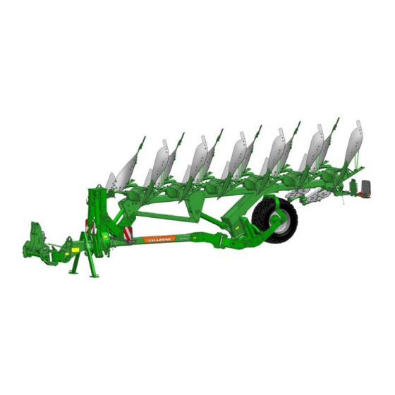
- Page 1 Operating manual Hektor Trailed reversible plough Read and observe this operating manual before using MG6213 the implement for the first time! BAG0186.1 07.19 Keep it in a safe place for future Printed in Germany use!
- Page 2 Only this way, you would be satisfied both with the machine as also with yourself. To achieve this is the purpose of this instruction manual. Leipzig-Plagwitz 1872. Hektor BAG0186.1 07.19...
- Page 3 Postfach 51 D-49202 Hasbergen, Germany Tel.: + 49 (0) 5405 50 1-0 E-mail: amazone@amazone.de Spare part orders Spare parts lists are freely accessible in the spare parts portal at www.amazone.de. Please send orders to your AMAZONE dealer. Hektor BAG0186.1 07.19...
- Page 4 No claims can be made based on differences in the specifications, figures or descriptions. Figures serve as a reference and are to be understood as representations of the principle. If you want to sell the implement, ensure that the operating manual is supplied with the implement. Hektor BAG0186.1 07.19...
- Page 5 We update our operating manuals regularly. Your suggestions for improvement help us to create ever more user-friendly operating manuals. AMAZONEN-WERKE H. DREYER GmbH & Co. KG Postfach 51 D-49202 Hasbergen, Germany Tel.: + 49 (0) 5405 50 1-0 E-mail: amazone@amazone.de Hektor BAG0186.1 07.19...
-
Page 6: Table Of Contents
Adjusting the working depth ....................38 Adjusting the pitch ......................... 39 Adjusting the track width ....................... 40 Adjusting the disc coulter ...................... 40 7.6.1 Disc coulter adjustment for automatic stone release ............41 Fertiliser skimmer ........................42 Hektor BAG0186.1 07.19... - Page 7 Installation and removal of hydraulic hose lines ..............62 10.9.5 Installation of hose valve chests with O-ring and union nut ........... 62 10.10 Bolt tightening torques ......................63 Malfunctions and their correction ............64 Hydraulic diagram..................65 Hektor BAG0186.1 07.19...
-
Page 8: Implement Description
Compliance with all the instructions in this operating manual. • Execution of inspection and maintenance work. • Exclusive use of genuine AMAZONE spare parts. Other uses to those specified above are forbidden and shall be considered as improper. For any damage resulting from improper use •... -
Page 9: General Safety Instructions
If the user discovers that a function is not working properly, then they must eliminate this fault immediately. If this is not the task of the user or if the user does not possess the appropriate technical knowledge, then they should report this fault to their superior (operator). Hektor BAG0186.1 07.19... - Page 10 • Unauthorised design changes to the implement. • Insufficient monitoring of implement parts which are subject to wear. • Improperly executed repairs. • Disasters due to the effects of foreign objects and force majeure. Hektor BAG0186.1 07.19...
-
Page 11: Representation Of Safety Symbols
Non-compliance with these instructions can cause faults on the implement or disturbance to the environment. NOTE Indicates handling tips and particularly useful information. These instructions will help you to use all the functions of your implement in the best way possible. Hektor BAG0186.1 07.19... -
Page 12: Organisational Measures
As well as all the safety information in this operating manual, comply with the general, national regulations pertaining to accident prevention and environmental protection. When driving on public roads and routes you should comply with the statutory road traffic regulations. Hektor BAG0186.1 07.19... -
Page 13: User Training
The personnel of a specialist workshop shall possess the appropriate knowledge and suitable aids (tools, lifting and support equipment) for carrying out the maintenance and repair work on the implement in a way which is both appropriate and safe. Hektor BAG0186.1 07.19... -
Page 14: Safety Measures In Normal Operation
Vehicles with an official type approval or with equipment connected to a vehicle with a valid type approval or approval for road transport according to the German road traffic regulations must be in the state specified by the approval. Hektor BAG0186.1 07.19... -
Page 15: Spare And Wear Parts And Aids
Immediately replace any implement parts which are not in a perfect state. Only use genuine AMAZONE spare and wear parts, or those approved by AMAZONEN-WERKE, so that the operating permit remains valid according to the national and international regulations. If... -
Page 16: Safety And Accident Prevention Regulations
21. Before leaving the tractor, lower the implement to the ground, switch off the engine, and remove the ignition key! 22. Before each transport journey, check the implement for any damage, material fatigue, as well as for safe functioning of relevant safety parts for road transport. Hektor BAG0186.1 07.19... - Page 17 40. Replacement parts must at least meet the technical requirements stipulated by the implement manufacturer! This is guaranteed by using original replacement parts. Hektor BAG0186.1 07.19...
-
Page 18: Warning Symbols And Other Labels On The Implement
2. The consequence of non-compliance with the risk avoidance instructions. For example: causes serious injuries to fingers or hands. 3. The risk avoidance instructions. For example: only touch implement parts when they have come to a complete standstill. Hektor BAG0186.1 07.19... -
Page 19: Positions Of Warning Symbols And Other Labels
General safety instructions 2.14.1 Positions of warning symbols and other labels Warning symbols The following diagrams show the arrangement of the warning symbols on the implement. Hektor BAG0186.1 07.19... - Page 20 Ensure that all other persons also keep a sufficient safety distance from the danger area of the implement as long as the tractor engine is running. MD 095 Before commissioning the implement read and observe the operating manual and the safety instructions carefully! Hektor BAG0186.1 07.19...
- Page 21 Secure the tractor and the implement against unintentional start-up and rolling before any intervention in the implement. • Depending on the type of intervention, read and understand the information in the relevant sections of this operating manual. Hektor BAG0186.1 07.19...
- Page 22 General safety instructions MD 114 This pictogram indicates a lubrication point. MD 199 The maximum operating pressure of the hydraulic system is 210 bar. Hektor BAG0186.1 07.19...
-
Page 23: Model Overview / Technical Data
Hektor 7+1-1000 8 furrows 3,630 kg Hektor 8-1000 8 furrows 3,610 kg Stone release: NON STOP hydraulic (compact accumulator): Hektor 5+1-1000 S 6 furrows 3,500 kg Hektor 6-1000 S 6 furrows 3,480 kg 100 cm 82 cm / 78 cm... -
Page 24: Preparations On The Tractor And Plough
§ 70 of the German Regulations Authorising the Use of Vehicles for Road Traffic and the required approval according to § 29, paragraph 3 of the German Road Traffic Regulations. Hektor BAG0186.1 07.19... -
Page 25: Data Required For The Calculation
Tractor wheel base See tractor operating manual or vehicle documents or measurement Distance between the centre of the rear axle See tractor operating manual or vehicle and the centre of the lower link connection documents or measurement Hektor BAG0186.1 07.19... -
Page 26: Calculation Of The Required Minimum Ballasting At The Front G
(Section 7.1.1.7). 4.1.6 Tyre load capacity Enter the double value (two tyres) of the approved load capacity (see, for example, tyre manufacturer's documentation) in the table (Section 7.1.1.7). Hektor BAG0186.1 07.19... -
Page 27: Table
(if required) attached to the tractor for the minimum front ballast (G V min • You must use a front weight, which is equal to at least the required minimum front ballast (G V min Hektor BAG0186.1 07.19... -
Page 28: Preparations On The Tractor
Lateral stabilisation of the lower links: Completely lock the lower link in its lateral movement. This setting also applies for ploughing and transport. (1) Running gear stop tap (2) Stop tap for track adjustment (3) Stop tap for turning Hektor BAG0186.1 07.19... -
Page 29: Traffic Safety Equipment
Traffic safety equipment Front lighting: (1) Reflector, white Rear lighting: (1) Reflector, yellow (2) Warning signs (3) Brake light and direction indicator (4) Reflector (triangular) (5) Number plate holder with lighting (6) Maximum permitted transport speed (km/h) Hektor BAG0186.1 07.19... -
Page 30: Coupling And Uncoupling The Implement
4. Couple and lock the top link. 5. Adjust the length of the top link so that the axle (1) is positioned vertically. 6. Couple the supply lines. 7. Raise both jacks and lock them. 8. Raise the implement using the running gear. Hektor BAG0186.1 07.19... -
Page 31: Uncoupling The Implement
7. Lower the 3-point frame until the top link is relieved. 8. Uncouple the top link. 9. Slightly raise the 3-point frame with the tractor lower link. 10. Secure the 3-point frame with the chain. 11. Uncouple the supply lines. 12. Uncouple the lower link. Hektor BAG0186.1 07.19... - Page 32 Coupling and uncoupling the implement Hektor BAG0186.1 07.19...
-
Page 33: Hydraulic Connections
Float position, free oil flow in the control unit Labelling Function Tractor control unit bigger Front furrow Double Yellow width acting (optional) smaller Working Double Right and left Green direction acting Single- Running gear Blue acting Single- Pre-tensioning of the stone release Beige acting (Option) Hektor BAG0186.1 07.19... -
Page 34: Coupling The Hydraulic Hose Lines
1. Swivel the actuation lever on the control unit on the tractor to float position (neutral position). 2. Release the hydraulic connectors from the hydraulic sockets. 3. Protect the hydraulic sockets from soiling by fitting the dust caps. 4. Hook the hydraulic connectors into the connector holders. Hektor BAG0186.1 07.19... -
Page 35: Road Transport
Always ensure sufficient steering and braking capacity! • When driving in curves, ensure that there is enough space between the tractor and the implement! • Observe the permitted transport dimensions according to traffic regulations! Hektor BAG0186.1 07.19... - Page 36 Pay attention to sufficient ground clearance. → This activates the shock absorber. 2. Close the stop taps. (1) Running gear hydraulic system (2) Hydraulic front furrow adjustment (3) Hydraulic turnover system Raise the implement to mid-height using the running gear. Hektor BAG0186.1 07.19...
-
Page 37: Adjusting The Plough
Any adjustments to cutting width is automatically passed on to leading tools such as the fertiliser skimmers, disc coulter, and support wheels (if present) and fit exactly to the new cutting width. No further adjustments whatsoever are required. Hektor BAG0186.1 07.19... -
Page 38: Front Furrow Width - Rough Adjustment To The Tractor Track Width
• the stop spindle on the running gear Secure the position of the stop spindle using a spring cotter pin. Adjust the depth so that the plough is horizontal during operation. Hektor BAG0186.1 07.19... -
Page 39: Adjusting The Pitch
The landsides and plough beams (2) must be perpendicular to the ground. (1) Front pitch stop To be able to turn the setting spindles, briefly apply pressure to the turning cylinder. This relieves the spindles. (1) Rear pitch stops Hektor BAG0186.1 07.19... -
Page 40: Adjusting The Track Width
When there are large quantities of crop residues, set the disc coulters further to the front on the holder. (4) Adjusting the distance from the share. Adjust the distance from the share by moving both disc coulters together on the holding bar. Hektor BAG0186.1 07.19... -
Page 41: Disc Coulter Adjustment For Automatic Stone Release
This distance is achieved by rotating the coulter shaft C. Rotation is enabled by loosening the bolt S2. Lateral swing of coulter is to be set using stop (B). Hektor BAG0186.1 07.19... -
Page 42: Fertiliser Skimmer
2 bolts. Use on stony soils is not advised (no stone release). Driving in curves forbidden! It is forbidden to drive in curves during operation due to overstraining of the implement! Hektor BAG0186.1 07.19... -
Page 43: Overload Safety
(Using check valve: on each compact accumulator, each cylinder can be individually disconnected from the central tubing). The tripping force can be adjusted during operation directly from the tractor using the control hydraulic system. Hektor BAG0186.1 07.19... - Page 44 Where required, the tripping force can be set via the tractor hydraulics and read from the pressure gauge. To protect against damage, the stone release must be fitted with a shear bolt. Hektor BAG0186.1 07.19...
-
Page 45: Hydraulic Stone Release With Central Pressure Setting
The pressure gauge shows the tripping pressure for all shares. (1) Stop tap (2) Pressure gauge Using the stop tap on the hydraulic cylinder, different tripping pressures can be applied to the shares also with central pressure setting. Hektor BAG0186.1 07.19... -
Page 46: Hydraulic Stone Release With Decentralised Pressure Setting
3. Actuate the tractor control unit. Set the desired tripping pressure. 4. Close the stop tap on the drawbar hydraulic cylinder (position 0). 5. Depressurise the pressure control hose. 6. Set all other shares in the same manner. Hektor BAG0186.1 07.19... -
Page 47: Use
3. Activate tractor control unit green. → Rotate the plough using the hydraulic turnover system. Ensure that the hydraulic hoses do not bend while rotating. Operate the hydraulic turnover system only from the tractor seat! Hektor BAG0186.1 07.19... -
Page 48: Cleaning, Maintenance And Repair
• Only use AMAZONE original spare parts. • Use only genuine AMAZONE replacement hoses, and hose clamps made of V2A for assembly. • Specialist knowledge is the requirement for carrying out testing and maintenance operations. This specialist knowledge is not given here in this operating manual. - Page 49 Read the operating manual of the tractor manufacturer to find out how to depressurise the system. The stored energy in the hydraulic accumulator can lead to serious injuries when working on the hydraulic system. Hydraulic pressures up to 400 bar! Only perform work on a depressurised system. Hektor BAG0186.1 07.19...
-
Page 50: Lubrication Schedule
Grease nipple Grease nipple Grease nipple Grease nipple Grease nipple Grease nipple Grease nipple (10) Grease nipple (11) Grease nipple (12) Grease nipple (13) Grease nipple (14) Grease nipple (15) Grease nipple (16) Grease nipple (17) lubricate Hektor BAG0186.1 07.19... - Page 51 Cleaning, maintenance and repair Hektor BAG0186.1 07.19...
-
Page 52: Cleaning
Do not clean the implement with warm water at ambient temperatures below 10°C. ο The nozzle spraying angle must be at least 25°. ο Do not use a spraying jet booster. ο Comply with safety regulations when working with pressure washers. Hektor BAG0186.1 07.19... -
Page 53: Maintenance Schedule - Overview
• Check inflation pressure, correct Support wheel if necessary • Check the bearing clearance on the wheel hubs Annually / 1000 operating hours Component Workshop work Servicing work page • Hydraulic accumulator Set the oil pressure Hektor BAG0186.1 07.19... -
Page 54: Depressurise The Hydraulic System
The system is only depressurised when • the implement in working position is supported on the ground. • the implement is not carried by the running gear. • the system including the hydraulic accumulator was depressurised using the tractor hydraulic system. Hektor BAG0186.1 07.19... -
Page 55: Setting The Oil Pressure On The Hydraulic Accumulator
(cylinder, accumulator, hose lines, tubing, etc.), depressurise the system. Before reducing the system pressure 1. Couple the plough Support the plough accordingly. Risk of overturning! The non-stop stone releases are additionally secured by shear bolts. See page 43. Hektor BAG0186.1 07.19... -
Page 56: Checking The Condition Of The Shares And Wear Parts
Replace worn shares and mould boards promptly to prevent damage to the frogs or supporting parts. The same applies to leading tools, if equipped 10.6 Checking the shear bolts Check the bolts for tightness. Required tightening torque for the bolts: Hektor BAG0186.1 07.19... -
Page 57: Checking The Support Wheel
2. Loosen the axle attachment bolts on both sides. 3. Remove the wheel from the fork 4. Loosen the bolts that connect the rim to the running axle 5. Change the tyres 6. Install the rim and axle attachment bolts in the reverse sequence. Hektor BAG0186.1 07.19... -
Page 58: Check Bearing Clearance On Wheel Hubs
• Repair paint damage to protect from corrosion! • Park the implement protected from the weather, but not close to mineral fertilisers / salts or in stables. • Grease all lubrication points and wipe off emerging grease. Hektor BAG0186.1 07.19... -
Page 59: Hydraulic System
• After skin contact: ο wash off with lots of water and soap. • After eye contact: ο flush eyes with the lids open for several minutes under flowing water. • After swallowing: ο seek medical treatment. Hektor BAG0186.1 07.19... -
Page 60: Labelling Of Hydraulic Hose Lines
• Replace the hydraulic hose lines if they are damaged or worn. Only use genuine AMAZONE hydraulic hose lines! • The hydraulic hose lines should not be used for longer than six years, including any storage time of maximum two years. Even... -
Page 61: Maintenance Intervals
Common causes for leaking hoses / pipes and connection pieces include: • missing O-rings or gaskets • damaged or badly fitting O-rings • brittle or deformed O-rings or gaskets • foreign bodies • badly fitting hose clamps Hektor BAG0186.1 07.19... -
Page 62: Installation And Removal Of Hydraulic Hose Lines
Cleaning, maintenance and repair 10.9.4 Installation and removal of hydraulic hose lines You must • only use genuine AMAZONE replacement hoses. These replacement hoses withstand the chemical, mechanical and thermal strains. • always use hose clamps made from V2A for fitting hoses. -
Page 63: Bolt Tightening Torques
1500 1800 M 27x2 1150 1600 1950 M 30 1450 2000 2400 M 30x2 1600 2250 2700 20.6 40.7 70.5 Coated bolts have different tightening torques. Observe the specific data for tightening torques in the maintenance section. Hektor BAG0186.1 07.19... -
Page 64: Malfunctions And Their Correction
Reduce the pitch • Install additional glide plates • The plough will not turn Replace the implement coupling plug if it does not fit for the tractor coupling part (opening stroke of the valve body) See page 47. Hektor BAG0186.1 07.19... -
Page 65: Hydraulic Diagram
Hydraulic diagram Hydraulic diagram Hektor BAG0186.1 07.19...
Need help?
Do you have a question about the Hektor and is the answer not in the manual?
Questions and answers