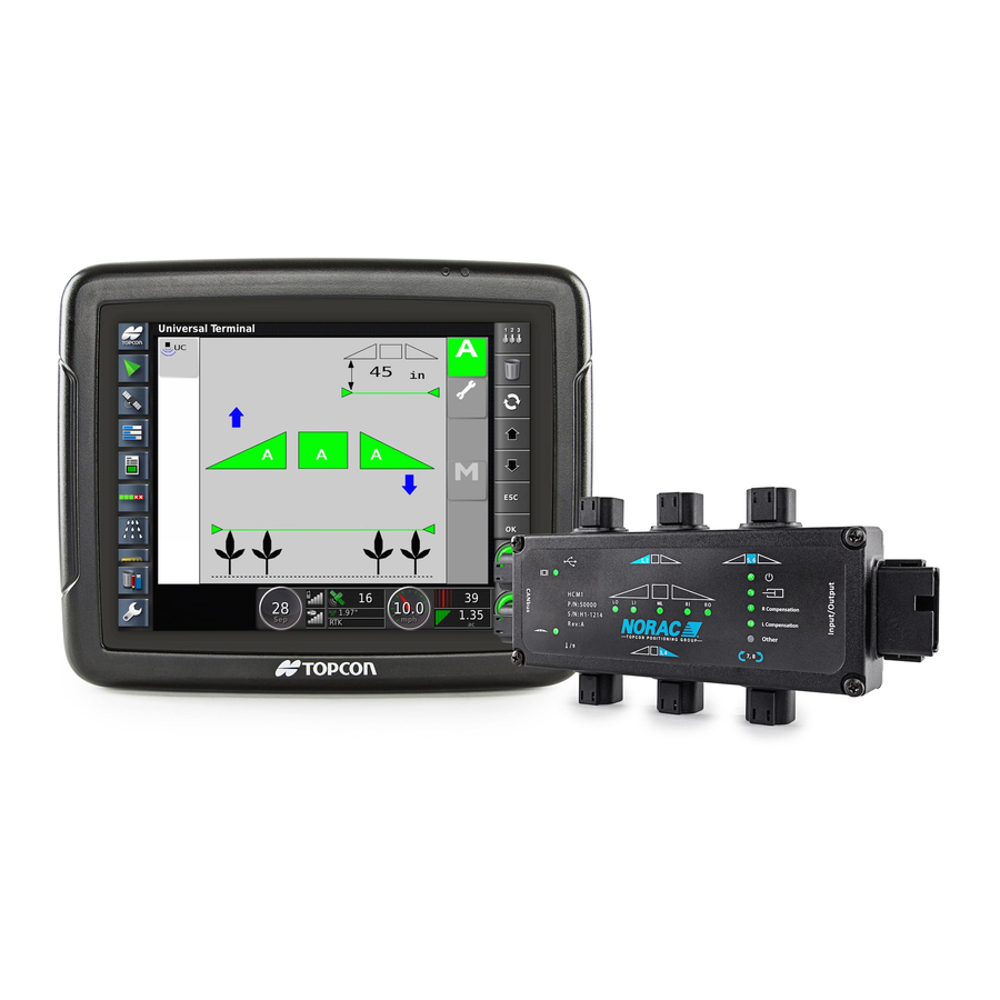
Norac UC7 Installation Manual
Generic unit, boom height control system
Hide thumbs
Also See for UC7:
- Installation manual (43 pages) ,
- Installation manual (35 pages) ,
- Installation manual (35 pages)
Advertisement
Advertisement
Table of Contents

Related Manuals for Norac UC7


Summary of Contents for Norac UC7
- Page 1 Generic Unit UC7 Boom Height Control System Installation Manual ...
- Page 2 Copyright 2019 by NORAC Systems International Inc. Reorder P/N: UC7‐BC‐GN01‐INST Rev C (Generic Unit) NOTICE: NORAC Systems International Inc. reserves the right to improve products and their specifications without notice and without the requirement to update products sold previously. Every effort has been made to ensure the accuracy of the information contained in this manual. The technical information in this manual was reviewed at the time of approval for publication. ...
-
Page 3: Table Of Contents
WWW.NORAC.CA PRECISION DEFINED Contents Introduction .......................... 1 Technical Specifications ...................... 2 Parts Overview ........................ 3 Pre‐Installation Checklist ....................... 8 Hydraulic Installation ...................... 9 Ultrasonic Sensor Installation .................... 14 Electronic Installation ...................... 20 Software Setup ........................ 24 Cable Schematics ......................... 25 ... -
Page 4: Introduction
WWW.NORAC.CA PRECISION DEFINED 1 Introduction Congratulations on your purchase of the NORAC Boom Height Control System. This system is manufactured with top quality components and is engineered using the latest technology to provide operating reliability unmatched for years to come. When properly used the system can provide protection from sprayer boom damage, improve sprayer efficiency, and ensure chemicals are applied correctly. Please take the time to read this manual completely before attempting to install the system. A thorough ... -
Page 5: Technical Specifications
WWW.NORAC.CA PRECISION DEFINED 2 Technical Specifications CAN ICES‐3(A)/NMB‐3(A) This Class A digital apparatus complies with Canadian ICES‐003. Pursuant to EMC Directive – Article 9, this product is not intended for residential use. Table 1: System Specifications Supply Voltage (rated) 12VDC Supply Current (rated) 10A Hydraulic Pressure (maximum) 3300 psi Baud Rate 250 kbps Operating Temperature Range 0°C to 80°C Visit www.solutions.norac.ca for more system Page 2 installation and troubleshooting info. ... -
Page 6: Parts Overview
WWW.NORAC.CA PRECISION DEFINED 3 Parts Overview 3.1. Electronic Installation Overview The following diagrams illustrate the GN01 kit specific parts of the NORAC UC7™ system. Interface cables, power cables, hoses and fittings are shown in this manual and may not be included. Cables are available separately from NORAC. Please refer to the UC7 Cable Ordering Guide (P/N: UC7‐BC‐CABLE‐GUIDE) for cable ordering information (available at www.norac.ca). Figure 1: Electronic Installation Overview Items shown in green and denoted with an asterisk (*) are not included and must be ordered separately. Items shown in BLUE are included in the display package and may not be exactly as shown. Visit www.solutions.norac.ca for more system Page 3 installation and troubleshooting info. ... - Page 7 WWW.NORAC.CA PRECISION DEFINED 3.2. Hydraulic Plumbing Schematic 3.2.1. Single Acting Figure 2: Single Acting Hydraulic Plumbing Schematic Items shown in green and denoted with an asterisk (*) are not included. Visit www.solutions.norac.ca for more system Page 4 installation and troubleshooting info. ...
- Page 8 WWW.NORAC.CA PRECISION DEFINED 3.2.2. Double Acting Figure 3: Double Acting Hydraulic Plumbing Schematic Items shown in green and denoted with an asterisk (*) are not included. Visit www.solutions.norac.ca for more system Page 5 installation and troubleshooting info. ...
- Page 9 50300 ULTRASONIC MAX SENSOR 3 E11 43765 NETWORK COUPLER 8‐WAY 1 E12 43764 NETWORK COUPLER 2‐WAY 1 E20 43764T NETWORK COUPLER 2‐WAY WITH TERMINATOR 2 H10 44865‐34 HYDRAULICS FITTING KIT ‐ GN1 1 M02 UC7‐BC‐GN01‐INST MANUAL INSTALLATION UC7 GENERIC 1 M05 106706 MOUNTING CLIP HCM1 2 P01 106705 NETWORK 4 PIN CAVITY PLUG 3 P03 105882 NETWORK 6 PIN PLUG 4 V01 50902 VALVE ASSEM 2 STATION CC PROP DT 1 ...
- Page 10 WWW.NORAC.CA PRECISION DEFINED 3.3.1. Hydraulic Fitting Kit Details (P/N: 44865‐34) Item Part Number Name Quantity Picture F07 103312 MALE ADAPTER ‐ 6MB 6MJ 6 F08 44928 ORIFICE INSERT .047 IN ONE WAY 4 F09 104369 PLUG ‐ 6MBP 2 6 M B - 6 M OR X 90 Fitting Name Example: ANGLE SIZE IN °...
-
Page 11: Pre-Installation Checklist
WWW.NORAC.CA PRECISION DEFINED 4 Pre‐Installation Checklist The pre‐install checklist is necessary to check the existing sprayer functionality before the installation. Unfold the sprayer over a flat, unobstructed area (i.e. no power lines…etc.). Ensure all boom‐fold operations are functional (place a check mark in boxes below). Bring engine to field‐operational RPM and record below. Record the time (seconds) it takes for a full stroke for all boom functions. To ensure repeatable measurements, take the average of 3 trials. Not all sprayers will have the functions listed below in Figure 4. Ensure the boom has sufficient travel so it does not contact the ground during these tests. Figure 4: Pre‐Install Boom Speeds Visit www.solutions.norac.ca for more system ... -
Page 12: Hydraulic Installation
Component failure due to oil contamination is not covered under the NORAC system warranty. It is recommended that a qualified technician perform the hydraulic installation. Before assembling the valve block, identify if the sprayer tilt cylinders are single acting or double acting. A single acting cylinder will only have one hose running to it, while a double acting cylinder has two hoses ... - Page 13 WWW.NORAC.CA PRECISION DEFINED 5.2. Valve Block Assembly: Double Acting On a clean surface remove the plastic plugs from the block. Install the 6MB‐6MJ (F07) fittings into the “P” and “T” ports. Tighten to 18 ft‐lbs (24 Nm). Insert the two orifices (F08) into the “B” ports with the notch facing outward. Install the 6MB‐6MJ (F07) fittings into the “B” ports. Tighten to 18 ft‐lbs (24 Nm). Insert the two orifices (F08) into the “A” ports with the notch facing in. Install the 6MB‐6MJ (F07) fittings into the “A” ports. Tighten to 18 ft‐lbs (24 Nm). Fitting F07 is a special fitting; if an additional coupler is required, contact NORAC. Figure 6: NORAC Valve Block Details Visit www.solutions.norac.ca for more system Page 10 installation and troubleshooting info. ...
- Page 14 WWW.NORAC.CA PRECISION DEFINED 5.3. Valve Block Mounting Mount the NORAC valve block onto the sprayer near the existing valve block. Insert the M8 mounting studs into the block using a hex nut to hold the stud. The manifold mounting holes are M8‐1.25 x 19mm (0.75”) deep. If bolts are used instead of the studs, ensure the bolts thread in at least 10mm (3/8”). Apply a light coating of the supplied Permatex Anti‐seize grease to all threaded parts upon installation. Use the remaining hardware to secure the block to the sprayer. Cut off any excess stud length if necessary. Figure 7: Valve Block Mounting Visit www.solutions.norac.ca for more system Page 11 installation and troubleshooting info. ...
- Page 15 5.4. Hydraulic Plumbing: Single Acting From this point on in the installation the booms will be inoperative until the hydraulics are fully installed. After the NORAC valve is mounted, the hydraulic hoses and fittings can be plumbed. The plumbing for the hydraulic circuit is shown schematically in Figure 2. Disconnect the tilt raise lines from the sprayer valve block and insert the two tees (*F02) between the hoses and the valve block. Connect two hydraulic hoses (*H02) from the free ends of the tees to the NORAC valve block. The raise lines must be connected to the “B” ports. If there are any accumulators on the tilt hydraulic circuits, ensure there is a 2‐way orifice in the accumulator fitting. There must be no other orifices in the hydraulic circuit between the NORAC valve block and the tilt cylinders. Disconnect the pressure and tank lines from the sprayer valve block and insert the two tees (*F01) between the hoses and the valve block. Connect two hydraulic hoses (*H01) from the free ends of the tees to the pressure and tank port on the NORAC valve block. Start up the sprayer and test the sprayer’s functionality. Unfold the booms and raise/lower each boom and the main section. Ensure that there are no leaks. ...
- Page 16 Disconnect the tilt raise and lower lines from the sprayer valve block and insert the four tees (*F02) between the hoses and the valve block. Connect four hydraulic hoses (*H02) from the free ends of the tees to the NORAC valve block. The raise lines must be connected to the “B” ports and the lower lines must be connected to the “A” ports. If there are any accumulators on the tilt hydraulic circuits, ensure there is a 2‐way orifice in the accumulator fitting. There must be no other orifices in the hydraulic circuit between the NORAC valve block and the tilt cylinders. Disconnect the pressure and tank lines from the sprayer valve block and insert the two tees (*F01) between the hoses and the valve block. Connect two hydraulic hoses (*H01) from the free ends of the tees to the pressure and tank port on the NORAC valve block. ...
-
Page 17: Ultrasonic Sensor Installation
WWW.NORAC.CA PRECISION DEFINED 6 Ultrasonic Sensor Installation 6.1. Ultrasonic Sensor Mounting Guidelines The following guidelines will ensure optimal sensor performance and prevent sensor measurement. In its lowest position, the sensor must be 9 inches (230 mm) or more from the ground. Ensure that there are no obstructions within a 12 inch (300 mm) diameter circle projected directly below the center of the sensor. The sensor should be approximately vertical at normal operating heights. Figure 9: Bracket Mounting Guidelines Figure 8: Sensor Mounting Guidelines 6.2. Low Profile Bracket Mounting Guidelines Minimize the distance between the bolts to prevent bending the bracket and prevent the bracket from loosening over time. Ensure the bracket is mounted tight against the bottom of the boom, minimizing the distance between the boom structure and the angled flange. A problem can arise if a sensor is not mounted correctly. This may only become apparent once the control system is switched from soil to crop mode. Be careful that the sensor bracket does not collide with any other part of the boom when the boom is folded to transport position. If possible, mount the sensor brackets while the booms are folded to ensure they will not cause interference. Visit www.solutions.norac.ca for more system Page 14 installation and troubleshooting info. ... - Page 18 WWW.NORAC.CA PRECISION DEFINED 6.3. Wing Sensor Installation If installing a three sensor system, refer to Section 6.3.1. If installing a five sensor system (severe terrain option), refer to Section 6.3.2. 6.3.1. Installation of a Three Sensor System When installing the MAX Sensors™ (E07), start with the smallest serial number on the left‐hand side and proceed to the largest serial number on the right‐hand side. Each sensor has a serial number stamped on the sensor housing. Apply a light coating of the supplied Permatex Anti‐seize grease to all threaded parts upon installation. Figure 10: Sensor Serial Number Arrangement The sensor bracket should be oriented forward (ahead of the boom). Typically, the best mounting location for the wing sensor brackets will be near the end of the boom tips, approximately two feet (0.6 m) from the end. Mount the MAX sensors (E07) into the sensor brackets. Run the sensor cable through hole in the back of the bracket. Ensure the cable is clear of moving parts and will not be damaged during folding. Visit www.solutions.norac.ca for more system Page 15 installation and troubleshooting info. ...
- Page 19 WWW.NORAC.CA PRECISION DEFINED Connect cables C05 to the 8‐way coupler and route along the boom to the outer wing sensors. At the sensor brackets, attach a 2‐way coupler with terminator (E20) to the sprayer boom. The 2‐way coupler with terminator is the white 2‐way coupler. Plug the sensor and the CANbus cable into the terminator. Front Figure 11: Bracket Mounting Example Visit www.solutions.norac.ca for more system Page 16 installation and troubleshooting info. ...
- Page 20 WWW.NORAC.CA PRECISION DEFINED 6.3.2. Installation of a Five Sensor System (Severe Terrain Option) When installing the MAX Sensors™ (E07), start with the smallest serial number on the left‐hand side and proceed to the largest serial number on the right‐hand side. Each sensor has a serial number stamped on the sensor housing. Figure 12: Sensor Serial Number Arrangement The sensor bracket should be oriented forward (ahead of the boom). Mount the outer wing sensor brackets as described in Section 6.3.1, step 2. Mount the inner wing sensor brackets onto the boom half way between the tip and center of the sprayer. Mount the MAX sensors (E07) into the sensor brackets. Run the sensor cable through hole in the back of the bracket. Ensure the cable is clear of moving parts and will not be damaged during folding. Connect cables C05 to the 8‐way coupler and route along the boom to the outer sensor bracket. At the outer sensor brackets, attach a 3‐way coupler (E10) to the sprayer boom. Connect cables C05 and the sensor cable to the 3‐way coupler. Connect cables C06 to the 3‐way coupler (E10) and route along the boom to the inner wing sensors. Visit www.solutions.norac.ca for more system Page 17 installation and troubleshooting info. ...
- Page 21 WWW.NORAC.CA PRECISION DEFINED At the inner sensor brackets, attach a 2‐way coupler with terminator (E20) to the sprayer boom. The 2‐ way coupler with terminator is the white 2‐way coupler. Plug the sensor and the CANbus cable into the terminator. Visit www.solutions.norac.ca for more system Page 18 installation and troubleshooting info. ...
- Page 22 WWW.NORAC.CA PRECISION DEFINED 6.4. Main Lift Sensor Installation The main lift mounting bracket (B21) is the bracket with the longer mounting flange. There are a variety of ways to mount the main lift bracket on most sprayers. The bracket should position the sensor approximately in the center of the sprayer, forward of the boom. An example of this mounting is illustrated in Figure 14. Front Figure 13: Bracket Mounting Example Mount the MAX sensor to the main lift bracket. Run the sensor cable through the hole and behind the bracket. Figure 14: Example Mounting of the Main Lift Bracket Ensure the bracket does not collide with any other part of the sprayer throughout the full range of main lift motion. Visit www.solutions.norac.ca for more system Page 19 installation and troubleshooting info. ...
-
Page 23: Electronic Installation
WWW.NORAC.CA PRECISION DEFINED 7 Electronic Installation 7.1. HCM1 Installation Verify the valve coil connectors are oriented vertically (Figure 15). Loosening the large plastic nut will allow the connector to be rotated. Figure 15: Align Coils Output Number Normal Function 1,2 Left Up and Down 3,4 Right Up and Down 5,6 Main Up and Down 7,8 Roll CW and CCW Figure 16: HCM1 Connections Figure 17: HCM1 Label Lay the longer branch of the valve cables (C10) across the coils with one 4‐pin connector on each side. Do not connect the cables at this time. Visit www.solutions.norac.ca for more system Page 20 installation and troubleshooting info. ... - Page 24 WWW.NORAC.CA PRECISION DEFINED Figure 18: Cables Under Mounting Clips (Side View) Figure 19: Cables Laid Across Valve Coils (Top View) Place the HCM1 (E01) between the valve coils. Orient the 6‐pin Deutsch (CANbus) connectors towards the “P” and “T” ports with the large label and LEDs facing up. Slide the mounting clips over the connectors of the HCM1 and the valve coil connectors. This may require flexing the plastic bracket slightly. Ensure the clip is pushed over the connectors far enough to allow the clips to engage behind the valve connectors. Connect the valve cables (C10) to the valve coils and the HCM1. The cable connected to the left connector (1,2) should be connected to the coil closest to the “P” and “T” ports. The cable connected to the right connector on the HCM1 (3,4) should be connected to the coil furthest from the “P” and “T” ports. Figure 20: HCM1 and Clip Installation Connect the temperature probe (C11) to the HCM1 (temp/9 connector). Connect the temperature probe to the hole labelled “TP” on the valve block using the supplied 3/8” x 1/2” (9.5 mm x 25 mm) bolt (Figure 21). Insert 4‐pin plugs (P01) into any unused connectors on the HCM1. Visit www.solutions.norac.ca for more system Page 21 installation and troubleshooting info. ...
- Page 25 WWW.NORAC.CA PRECISION DEFINED Figure 21: Valve Block with Temperature Probe Installed The interface cable (C20) is ordered separately from this kit. Please refer to the UC7™ Cable Ordering Guide (P/N: UC7‐BC‐CABLE‐GUIDE) for cable ordering information (available at www.norac.ca). Connect the 12‐pin connector on cable C20 to the HCM1. Tee the connectors on cable C20 into the left up, left down, right up, right down, main up, and main down functions. Ensure that all unused connectors are plugged with the plugs provided. The battery cable (C30) is ordered separately from this kit. Please refer to the UC7 Cable Ordering Guide (P/N: UC7‐BC‐CABLE‐GUIDE) for cable ordering information (available at www.norac.ca). Visit www.solutions.norac.ca for more system Page 22 installation and troubleshooting info. ...
- Page 26 WWW.NORAC.CA PRECISION DEFINED 7.2. Cabling Connections Fasten the 8‐way coupler to the boom with cable ties. Connect cable C02 between the 8‐way coupler (E11) and the 6‐pin NORAC bus connector on the HCM1. NORAC Bus Figure 22: NORAC Bus Location Connect the main lift sensor to the 8‐way coupler using cable C01 and a 2‐way coupler (E12). Cable C01 and item E12 may not be needed if the 8‐way coupler is mounted close enough to the main lift sensor. Insert the 6 pin plugs (P03) into the remaining receptacles of the 8‐way coupler. Figure 23: Cabling and Parts Layout Visit www.solutions.norac.ca for more system Page 23 installation and troubleshooting info. ...
-
Page 27: Software Setup
WWW.NORAC.CA PRECISION DEFINED 8 Software Setup Start up the sprayer and test the sprayer’s functionality. The display terminal does not need to be powered on for the original boom function switches to operate. Unfold the booms and raise/lower each boom and the main section. Confirm that the cabling and hoses do not pinch, stretch or bind over the entire range of motion. If any functions do not work, review the hydraulic and electrical portions of this manual to check for proper installation. Turn on the power for the display terminal using the switch on the side. The procedure for the installation of the UC7™ Boom Height Control system is now complete. Begin the Automatic System Setup procedure as described in the UC7 Technical Operation Manual. For optimal performance of the system, there should be very little play at the hitch clevis. The addition of polymer washers can help tighten up this connection (Figure 24). Washers Figure 24: Hitch Point Visit www.solutions.norac.ca for more system Page 24 installation and troubleshooting info. ... -
Page 28: Cable Schematics
WWW.NORAC.CA PRECISION DEFINED 9 Cable Schematics 9.1. Item C01: 43220‐01 ‐ Cable Network 14 AWG – 1m 9.2. Item C02: 43220‐03 ‐ Cable Network 14 AWG – 3m Visit www.solutions.norac.ca for more system Page 25 installation and troubleshooting info. ... - Page 29 WWW.NORAC.CA PRECISION DEFINED 9.3. Item C05: 43210‐20 ‐ Cable Network 18 AWG – 20m Visit www.solutions.norac.ca for more system Page 26 installation and troubleshooting info. ...
- Page 30 WWW.NORAC.CA PRECISION DEFINED 9.4. Item C10: 50130‐01 ‐ Cable Valve 4‐Pin DT to 2‐Pin DT 9.5. Item C11: 50120‐01 ‐ Cable Temperature Probe Visit www.solutions.norac.ca for more system Page 27 installation and troubleshooting info. ...
- Page 31 TOPCON Agriculture Canada 3702 Kinnear Place Saskatoon, SK S7P 0A6 TOPCON Agriculture Americas W5527 Hwy 106 Fort Atkinson, WI 53538 TOPCON Precision Agriculture Europe Avenida de la industria, 35, Tres Cantos, España Spain Support Phone: 888 979 9509 E‐mail: tasupportn@topcon.com Web: www.norac.ca ...
Need help?
Do you have a question about the UC7 and is the answer not in the manual?
Questions and answers