Table of Contents
Advertisement
Quick Links
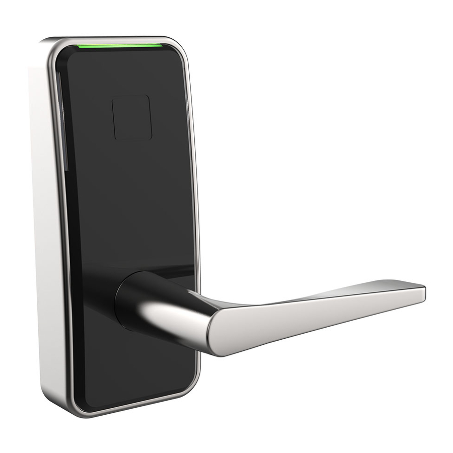
Saffire LX-I Installation Guide for door
thickness 1 3/8" to 2 1/8"
For thicker door please see order guide.
1.
Please read and follow all directions carefully.
2.
This lock is not designed to be used on emergency exit doors.
3.
Carefully inspect glass, door frame, door etc. to ensure the recommended procedure will not cause damage.
dormakaba standard warranty does not cover damages cause by installation.
4.
Wear safety glasses when making the holes.
5.
All the following operations and testing of the lock to be done with door open.
1A - INSTALL STRIKE ON WOOD FRAME
TOOLS REQUIRED
•
Safety glasses
•
1/2" (13mm) Chisel
Install long screws
•
1/8" (3mm) Drill Bit
on door stop side
•
5/32" (4mm) Drill Bit
•
1" (25mm) Drill bit or Hole Saw
•
2 1/8" (54mm) Drill bit or Hole
Saw
•
Drill
•
Awl or Center Punch
•
Screwdriver, 1/8" Slotted
For maximum
•
Philips Screwdriver #2
security, install
•
Adjustable Square
reinforcing plate
•
Tape Measure
1C - DOOR PREPARATION
A = Backset = 2.3/4"(70mm) or 2 3/8" (60mm)
A
4" or
5-1/2"
1" (25mm )
2 1/8" (54mm ) Hole saw
2.
ADJUST BACKSET OF DEADBOLT
2
1
3
DO NOT REMOVE TAPE
The deadbolt is pre-set at 2 ¾" (70mm) backset. Proceed as
illustrated to change to 2 ⅜" (60mm) backset, if required.
WARNING
1B - INSTALL STRIKE ON STEEL FRAME
Door stop
1.
Determine which template fits your Saffire LX-I lock installation, either
2 3/8" (60mm) or 2 3/4" (70mm) backset, 4" or 5 1/2" center to center.
2.
Place appropriate template (supplied) onto door and mark holes.
3.
Drill holes as per dimensions on the template. The 1" (25 mm) hole to
be on the center line of door thickness.
4.
Mortise door edge for dead bolt face plate and latch bolt face plate.
5.
Drill 2 1/8" from both sides of the door to prevent unsightly damage.
3.
INSTALL DEADBOLT IN DOOR
Do not remove tape
2X
18
Slot at the bottom
ITEM
QTY
DESCRIPTION
NO.
1
1
FRONT UNIT ZINC HOUSING
2
1
GASKET - FRONT LOCK HOUSING
3
1
TAIL PIECE
4
1
BACK PLATE - INSIDE TRIM
5
1
INSIDE TRIM COVER ASSEMBLY
6
1
DEAD BOLT
7
1
LATCH
8
1
HANDLE ASSEMBLY - OUTSIDE
9
1
STRIKER PLATE AND DUST BOX KIT
10
2
REINFORCING PLATE
11
2
DUST BOX
12
1
STRIKER PLATE
13A
1
SPINDLE ASSEMBLY
13B
1
SPINDLE & RETAINING RING ASSEMBLY
14
1
MESSENGER CABLE (OPTIONAL)
15
1
POWER CABLE
16
1
EXTENSION CABLE (OPTIONAL)
1
2
3
14
15
12
8
13A
21
11
10
9
27
28
PART LIST & LOCK DIAGRAM
ITEM
QTY
DESCRIPTION
NO.
17
3
PAN HEAD SCREW PHILLIPS, 10-24 x 1-1/4"
18
2
WOOD SCREW PHILLIPS, #8 X 1"
19
4
FLAT HEAD SCREWPHILLIPS, 8-32 X 1/2"
20
2
FLAT HEAD SCREWPHILLIPS, 8-32 X 7/32"
21
2
WOOD SCREW PHILLIPS, #8 X 3"
22
1
PAN HEAD SCREWTORX, 6-32 X 3/16"
23
3
AA BATTERY
24
2
PAN HEAD SCREW PHILLIPS 8-32 X 3/4" OR 1 1/4"
25
2
PAN HEAD SCREW PHILLIPS 6-32 X 1/2"
26
1
REMOVABLE COVER
27
4
COMBO SCREW PHILLIPS #8 X 1"
28
2
COMBO SCREW PHILLIPS #8 X 1"
20
18
6
19
4
17
16
23
5
dormakaba Canada inc.
7301 Boul Décarie
27
7
13B
22
24
Montréal QC H4P 2G7
Canada
1-877-468-3555
www.kabalodging.com
Please continue on next page.
25
26
Advertisement
Table of Contents

Subscribe to Our Youtube Channel
Related Manuals for Dormakaba Saffire LX-I


Summary of Contents for Dormakaba Saffire LX-I
- Page 1 1C - DOOR PREPARATION A = Backset = 2.3/4"(70mm) or 2 3/8" (60mm) Determine which template fits your Saffire LX-I lock installation, either 2 3/8" (60mm) or 2 3/4" (70mm) backset, 4" or 5 1/2" center to center. Place appropriate template (supplied) onto door and mark holes.
- Page 2 INSTALL INSIDE TRIM ASSEMBLY ADJUST LOCK HANDING ON OUTSIDE HOUSING ASSEMBLY INSTALL 3 TOP SCREWS FIRST TO FRONT LOCK ASSEMBLY THEN INSTALL IN PLACE LEVER & ROSE ASSEMBLY. INSTALL 2X BOTTOM SCREW TO LEVER & ROSE ASSEMBLY. Hold inner cam in place, groove always points to 12 o'clock. OUTSIDE &...
- Page 3 10. INSTALL INSIDE TRIM ASSEMBLY IF SPINDLE IS DISCONNECTED FROM LEVER, RE-INSERT SPRING IN LEVER AS FOLLOW: PUSH THE SPRING LIGHTLY INSIDE LEVER HOLE AND GENTLY TWIST THE SPINDLE AND SPRING ASSEMBLY 2 OR 3 TURNS CAM HANDING INDICATOR COUNTERCLOWISE THEN PRESS THE SPINDLE ALL THE WAY IN. CAM HANDING INDICATOR FOR A RIGHT HAND SIDE LOCK, IT SHALL BE POSSIBLE TO ALIGN CAM SLOT VERTICALY AS SHOWN.
Need help?
Do you have a question about the Saffire LX-I and is the answer not in the manual?
Questions and answers
what are the meanings of the light colors on the lock when activated
what does flashing yellow light indicate