Brocade Communications Systems 6510 Hardware Installation Manual
Hide thumbs
Also See for 6510:
- Reference manual (370 pages) ,
- Administrator's manual (64 pages) ,
- Hardware reference manual (62 pages)
Table of Contents
Advertisement
Quick Links
Advertisement
Table of Contents

Subscribe to Our Youtube Channel
Related Manuals for Brocade Communications Systems 6510


Summary of Contents for Brocade Communications Systems 6510
- Page 1 53-1002174-10 08 May 2015 Brocade 6510 Hardware Installation Guide...
- Page 2 United States government. The authors and Brocade Communications Systems, Inc. assume no liability or responsibility to any person or entity with respect to the accuracy of this document or any loss, cost, liability, or damages arising from the information contained herein or the computer programs that accompany it.
-
Page 3: Table Of Contents
Platform capabilities................11 Platform components................12 Facility requirements..................13 Port side of the Brocade 6510.................14 Nonport side of the Brocade 6510..............15 Brocade 6510 Installation and Configuration................17 Items included with the Brocade 6510............17 Installation and safety considerations............. 17 Installation precautions............... - Page 4 Determining the need to replace a power supply and fan assembly..................45 Time Required...................45 Items Required..................45 Removing a power supply and fan assembly........46 Replacing a power supply and fan assembly........47 Brocade 6510 Switch Technical Specifications..............49 Regulatory Statements......................57 BSMI statement (Taiwan)................57 Canadian requirements.................57 CE Statement....................57 China CC statement..................58 China ROHS....................
-
Page 5: Preface
Identifies command names, keywords, and command options. italic text Identifies a variable. value In Fibre Channel products, a fixed value provided as input to a command option is printed in plain text, for example, --show WWN. Brocade 6510 Hardware Installation Guide 53-1002174-10... -
Page 6: Notes, Cautions, And Warnings
DANGER A Danger statement indicates conditions or situations that can be potentially lethal or extremely hazardous to you. Safety labels are also attached directly to products to warn of these conditions or situations. Brocade 6510 Hardware Installation Guide 53-1002174-10... -
Page 7: Brocade Resources
OEM/Solution Provider for all of your product support needs. ® • OEM/Solution Providers are trained and certified by Brocade to support Brocade products. • Brocade provides backline support for issues that cannot be resolved by the OEM/Solution Provider. Brocade 6510 Hardware Installation Guide 53-1002174-10... -
Page 8: Document Feedback
• By sending your feedback to documentation@brocade.com. Provide the publication title, part number, and as much detail as possible, including the topic heading and page number if applicable, as well as your suggestions for improvement. Brocade 6510 Hardware Installation Guide 53-1002174-10... -
Page 9: About This Document
• An illustration indicating the Brocade 6510 port groups and port numbers is added. • The Brocade 6510 switch does not configure ports as FL_Ports and therefore all references to the "FL_Port (fabric loop enabled)" is removed. • The Brocade 6510 does not support enclosed cabinets and hence all the references to the cabinets are changed to EIA racks. - Page 10 What’s new in this document Brocade 6510 Hardware Installation Guide 53-1002174-10...
-
Page 11: Brocade 6510 Introduction
Nonport side of the Brocade 6510.................. 15 Brocade 6510 overview The Brocade 6510 is a 48-port auto-sensing 2, 4, 8, or 16 Gbps as well as 10 Gbps Fibre Channel (FC) switch that delivers the latest Brocade single-chip architecture for Fibre Channel Storage Area Networks (SANs). -
Page 12: Platform Components
• An RJ45 10/100 Bast T Ethernet system management port, in conjunction with EZSwitchSetup, that supports switch IP address discovery and configuration, eliminating the need to attach a serial cable to configure the switch IP address and greatly increasing the ease of use. Brocade 6510 Hardware Installation Guide 53-1002174-10... -
Page 13: Facility Requirements
• Real-time clock (RTC) with battery. • The Brocade EZSwitchSetup wizard that makes SAN configuration a three-step point-and-click task. Facility requirements The following table provides the facilities requirements that must be met for the Brocade 6510. TABLE 1 Facility Requirements... -
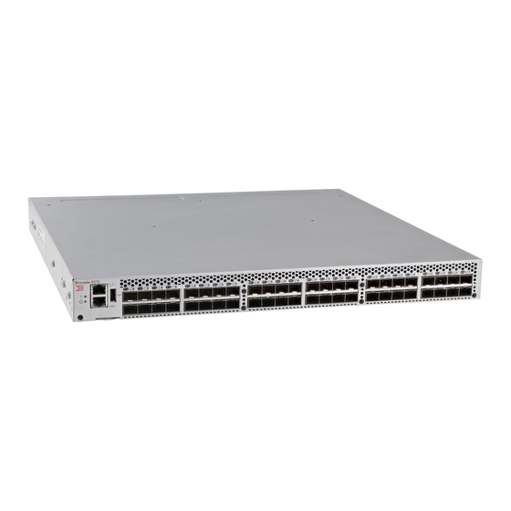
Page 14: Port Side Of The Brocade 6510
Port side of the Brocade 6510 Port side of the Brocade 6510 The port side of the Brocade 6510 includes the system status LED, console port, Ethernet port and LEDs, USB port, and Fibre Channel ports and the corresponding port status LEDs. -
Page 15: Nonport Side Of The Brocade 6510
Administrator's Guide. Nonport side of the Brocade 6510 The following figure shows the nonport side of the Brocade 6510, which contains the power supply including the power receptacle and power switch (only on AC PS) and fan assemblies. FIGURE 3 Nonport side of the Brocade 6510 with the AC power supply 1. - Page 16 Nonport side of the Brocade 6510 Brocade 6510 Hardware Installation Guide 53-1002174-10...
-
Page 17: Brocade 6510 Installation And Configuration
Items included with the Brocade 6510 The following items are included with the standard shipment of a fully-configured Brocade 6510. When you open the Brocade 6510 packaging, verify that these items are included in the package and that no damage has occurred during shipping: •... -
Page 18: Esd Precautions
Static electricity can damage the chassis and other electronic devices. To avoid damage, keep static-sensitive devices in their static-protective packages until you are ready to install them. Wear a wrist grounding strap connected to chassis ground (if the Brocade 6510 is plugged in) or a bench ground. -
Page 19: Rtc Battery
• A space that is one rack unit (1U) high; 4.45 cm (1.75 inches) high and 48.3 cm (19 inches) wide. • The two rack kit options for the Brocade 6510 use rails that are slimmer than standard rails to accommodate the slightly wider chassis. -
Page 20: Recommendations For Cable Management
• Use hook and loop style straps to secure and organize fiber optic cables. Items required for installation The following items are required for installing, configuring, and connecting the Brocade 6510 for use in a network and fabric: • Workstation with an installed terminal emulator, such as HyperTerminal •... -
Page 21: Standalone Installation For A Brocade 6510
Brocade 6510 configuration Once you have set up the Brocade 6510 in a rack or as a standalone switch, it is time to give it power and a basic configuration. If you are going to use the Brocade 6510 in a single-switch setup, you can use EZSwitchSetup to complete the basic configuration. -
Page 22: Creating A Serial Connection
/dev/ttya -9600 Switch IP address You can configure the Brocade 6510 with a static IP address, or you can use a DHCP (Dynamic Host Configuration Protocol) server to set the IP address of the switch. DHCP is enabled by default. The Brocade 6510 supports both IPv4 and IPv6. -
Page 23: Date And Time Settings
DHCP server. The DHCP client can only connect to a DHCP server that is on the same subnet as the switch. If your DHCP server is not on the same subnet as the Brocade 6510, use a static IP address. - Page 24 • yy is the year; valid values are 00 through 99 (values greater than 69 are interpreted as 1970 through 1999, and values less than 70 are interpreted as 2000-2069). switch:admin> date Fri Sep 29 17:01:48 UTC 2007 switch:admin> date "0927123007" Brocade 6510 Hardware Installation Guide 53-1002174-10...
- Page 25 The value ntp2 is the name of the second NTP server and is optional. The entire operand “<ntp1;ntp2> ” is optional; by default, this value is LOCL, which uses the local clock of the principal or primary switch as the clock server. switch:admin> tsclockserver LOCL switch:admin> tsclockserver "132.163.135.131" Brocade 6510 Hardware Installation Guide 53-1002174-10...
-
Page 26: Brocade Inter-Switch Link (Isl) Trunking
Brocade ISL Trunking is optional software that allows you to create trunking groups of ISLs between adjacent switches. Up to eight FC ports on the Brocade 6510 can be used as a trunking group to achieve speeds up to 128 Gbps (256 Gbps full duplex) for optimal bandwidth utilization and load balancing. -
Page 27: Access Gateway Default Port Mapping
• Ensure that no zoning or Admin Domain (AD) transaction buffers are active. If any transaction buffer is active, enabling Access Gateway mode will fail with the error, “Failed to clear Zoning/Admin Domain configuration.” Brocade 6510 Hardware Installation Guide 53-1002174-10... - Page 28 3. Enter ag --modeDisable to disable Access Gateway mode. 4. Enter the ag --modeshow command to verify that AG mode is disabled. switch:admin> ag --modeshow Access Gateway mode is NOT enabled Brocade 6510 Hardware Installation Guide 53-1002174-10...
-
Page 29: Brocade 6510 Operation
The switch runs POST by default each time it is powered on; it can take up to several minutes to boot and complete POST. To power the Brocade 6510 off, power off both power supplies by setting each power switch to “O”. All devices are returned to their initial state the next time the switch is powered on. -
Page 30: Led Locations
• One power supply/fan assembly LED on each power supply on the non-port side of the switch LED locations The following figure shows the port side of the Brocade 6510. The port status LEDs for the FC ports are arranged left and right to correspond to the upper and lower ports in each pair. Refer to... -
Page 31: Led Patterns
LED patterns FIGURE 6 LEDs on nonport side of Brocade 6510 with AC power supplies 1. Power supply/fan assembly #2 status LED 2. Power supply/fan assembly #1 status LED FIGURE 7 LEDs on nonport side of Brocade 6510 with DC power supplies 1. - Page 32 Recommended action Power supply/fan No light PS/fan is not receiving power or Verify the PS/fan is on and seated and assembly status is off. the power cord is connected to a functioning power source. Brocade 6510 Hardware Installation Guide 53-1002174-10...
-
Page 33: Post And Boot Specifications
3. Analyzes fabric. If any ports are connected to other switches, the switch participates in a fabric configuration. 4. Obtains a domain ID and assigns port addresses. 5. Constructs unicast routing tables. 6. Enables normal port operation. Brocade 6510 Hardware Installation Guide 53-1002174-10... -
Page 34: Interpreting Post Results
OS Administrator's Guide . For information about error messages, refer to the Fabric OS Message Reference. Brocade 6510 Maintenance The Brocade 6510 is designed for high availability and low failure; it does not require any regular physical maintenance. It includes diagnostic tests and field-replaceable units, described in the following sections. - Page 35 SFP+ into the upper row of ports is with the gold edge down. The correct position to insert an SFP+ into the lower row of ports is with the gold edge up. FIGURE 8 Installing a 16 Gbps SFP+ in the upper row of port slot Brocade 6510 Hardware Installation Guide 53-1002174-10...
- Page 36 NOTE Diagnostic tests might temporarily lock the transmit and receive speed of the links during diagnostic testing. For information about specific diagnostic tests, see the Fabric OS Troubleshooting and Diagnostics Guide. Brocade 6510 Hardware Installation Guide 53-1002174-10...
-
Page 37: Brocade 6510 Management
Brocade 6510 Management Brocade 6510 Management You can use the management functions built into the Brocade 6510 to monitor the fabric topology, port status, physical status, and other information to help you analyze switch performance and to accelerate system debugging. - Page 38 Brocade 6510 Management Brocade 6510 Hardware Installation Guide 53-1002174-10...
-
Page 39: Power Supply, Fan Assembly, And Airflow Direction Support Matrix
Shipping FRU configuration per Intake FRU Labeled Exhaust FRU Labeled chassis Brocade 5100 23-0000092-xx Brocade 6505 23-0000092-xx Brocade 6510 23-0000092-xx 23-0000113-xx " E " Brocade 7800 23-0000092-xx Brocade VA-40FC 23-0000092-xx 23-1000032-xx " E " Brocade 6510 Hardware Installation Guide 53-1002174-10... - Page 40 Intake FRU Labeled Intake FRU Labeled chassis Brocade 5100 Brocade 6505 Brocade 6510 23-0000112-xx " I " Brocade 7800 Brocade VA-40FC NOTE NA = Hardware is not available and not supported in the current release. Brocade 6510 Hardware Installation Guide 53-1002174-10...
-
Page 41: Removal And Replacement Of Power Supplies And Fans
They are identical and fit into either slot. The Brocade 6510 fans are fixed inside the combined power supply and fan FRU to provide necessary airflow to cool the whole system. There are two fans located in each FRU. The system software sets fan speed and measures their speeds through the tachometer interface. -
Page 42: Removing And Replacing A Power Supply And Fan Assembly
Time Awake: 0 days (output truncated) The Brocade 6510 has two power supply and fan assemblies, as displayed in the following figure. Fabric OS identifies the assemblies from right to left on the nonport side as assembly 1 and assembly 2. - Page 43 4. Handle 5. Thumbscrew 6. DC Power plug receptacle (with cable retainer screws) 7. Power supply/fan assembly LED The following figure illustrates how to fasten the cables to the DC cable receptacles using the screws: Brocade 6510 Hardware Installation Guide 53-1002174-10...
- Page 44 NOTE If a power supply and fan assembly fails, leave the power supply and fan assembly in the Brocade 6510 until it can be replaced. Maintain both power supply and fan assembly in operational condition to provide redundancy. The following table describes the power supply and fan assembly status LED colors, behaviors, and actions required, if any.
-
Page 45: Determining The Need To Replace A Power Supply And Fan Assembly
,SP640-2P ,A ,TQ2H0000 br6510:admin> Time Required Replacing a power supply and fan assembly in the Brocade 6510 should require less than two minutes to complete. Items Required The following items are required to replace a power supply and fan assembly: •... -
Page 46: Removing A Power Supply And Fan Assembly
Complete the following steps to remove a combined power supply and fan assembly from a Brocade 6510. 1. To leave the Brocade 6510 in service while replacing a power supply and fan assembly, verify that the other power supply and fan assembly (the one not being replaced) has been powered on for at least four seconds and has a steady green LED. -
Page 47: Replacing A Power Supply And Fan Assembly
4. Captive screw Replacing a power supply and fan assembly Complete the following steps to replace a combined power supply and fan assembly in a Brocade 6510. CAUTION The power supply switch must be in the off position when you insert the power supply into the chassis. - Page 48 6. Verify that the LED on the new power supply and fan assembly displays a steady green light while the Brocade 6510 is operating. If the LED is not a steady green, ensure that the power supply is securely installed and seated properly.
-
Page 49: Brocade 6510 Switch Technical Specifications
Brocade 6510 Switch Technical Specifications This document highlights the features and specifications for the Brocade 6510 switch. System specifications System component Description Enclosure 1U, non-port side front-to-back exhaust airflow, power from back Power inlet Power supplies Dual, hot-swappable redundant power supplies with integrated system cooling fans... - Page 50 Brocade 6510 Switch Technical Specifications System component Description FCIP (IP over Fibre Complies with FC-IP 2.3 of FCA profile Channel) Port Status Bicolor LED (amber/green) Ethernet System component Description SFP GbE ports 10/100 Mbps Ethernet (24, 36, and 48 ports)
- Page 51 Brocade 6510 Switch Technical Specifications Weight and physical dimensions "System weight"Brocade 6510 switch: 9.16 kg (20.20 lb) with two power supply and fan assemblies, and no SFPs installed). Model Height Width Depth Weight (empty) Weight (fully loaded) Brocade 6510 4.30 cm 43.80 cm...
- Page 52 <10 ms 40 VDC- 60 VDC (range) Power consumption (typical configuration) NOTE A 200 VAC power supply is not supported on the Brocade 6510 switch. Model name @100 VAC input @200 VAC input @-48 VDC input Minimum Notes number of...
- Page 53 Fans at high speed. Power consumption (idle configuration) NOTE A 200 VAC power supply is not supported on the Brocade 6510 switch. Model name @100 VAC input @200 VAC input @-48 VDC input Minimum Notes number of...
- Page 54 Brocade 6510 Switch Technical Specifications Port speed (Gbps) Cable size Short wavelength Long wavelength Extended long (microns) (SWL) (LWL) wavelength (ELWL) 62.5 150 m (492 ft) 30 km (18.6 miles) 150 m (492 ft) (OM2) 380 m (1,264 ft) (OM3)
- Page 55 Brocade 6510 Switch Technical Specifications Serial port specifications (pinout RJ-45) Signal Description Not supported Not supported UART1_TXD Transmit data Logic ground Logic ground UART1_RXD Receive data Not supported Not supported Serial port specifications (protocol) Parameter Value Baud 9600 Data bits...
- Page 56 Brocade 6510 Switch Technical Specifications Regulatory compliance (EMC) • FCC Part 15, Subpart B (Class A) • EN 55022 (CE mark) (Class A) • EN 55024 (CE mark) (Immunity) for Information Technology Equipment • ICES-003 (Canada) (Class A) • AS/NZ 55022 (Australia) (Class A) •...
-
Page 57: Regulatory Statements
The standards compliance label on this device contains the CE mark which indicates that this system conforms to the provisions of the following European Council directives, laws, and standards: Brocade 6510 Hardware Installation Guide 53-1002174-10... -
Page 58: China Cc Statement
China CC statement • Electromagnetic Compatibility (EMC) Directive 2004/108/EEC • Low Voltage Directive (LVD) 2006/95/EC • EN50082-2/EN55024:1998 (European Immunity Requirements) ‐ EN61000-3-2/JEIDA (European and Japanese Harmonics Spec) ‐ EN61000-3-3 China CC statement Brocade 6510 Hardware Installation Guide 53-1002174-10... -
Page 59: China Rohs
Class A device (Broadcasting Communication Device for Office Use): This device obtained EMC registration for office use (Class A), and may be used in places other than home. Sellers and/or users need to take note of this. VCCI statement Brocade 6510 Hardware Installation Guide 53-1002174-10... - Page 60 This is a Class A product based on the standard of the Voluntary Control Council for Interference by Information Technology Equipment (VCCI). If this equipment is used in a domestic environment, radio disturbance might arise. When such trouble occurs, the user might be required to take corrective actions. Brocade 6510 Hardware Installation Guide 53-1002174-10...
-
Page 61: Caution And Danger Notices
Vérifiez que rien ne restreint la circulation d'air devant, derrière et sur les côtés du dispositif et GARDE qu'elle peut se faire librement. PRECAUCIÓN Asegúrese de que el flujo de aire en las inmediaciones de las partes anterior, laterales y posterior del instrumento no esté restringido. Brocade 6510 Hardware Installation Guide 53-1002174-10... - Page 62 VORSICHT Bevor Sie ein Kabel in einen Anschluss einstecken, entladen Sie jegliche im Kabel vorhandene elektrische Spannung, indem Sie mit den elektrischen Kontakten eine geerdete Oberfläche berühren. Brocade 6510 Hardware Installation Guide 53-1002174-10...
- Page 63 Never insert the power supply upside down. VORSICHT Beachten Sie mechanischen Führungen an jeder Seite des Netzteils, das ordnungegemäß in die Führungen gesteckt werden muss. Das Netzteil darf niemals umgedreht eingesteckt werden. Brocade 6510 Hardware Installation Guide 53-1002174-10...
-
Page 64: Danger Notices
Electrical dangers DANGER For safety reasons, the ESD wrist strap should contain a series 1 megaohm resistor. GEFAHR Aus Sicherheitsgründen sollte ein EGB-Armband zum Schutz von elektronischen gefährdeten Bauelementen mit einem 1 Megaohm-Reihenwiderstand ausgestattet sein. Brocade 6510 Hardware Installation Guide 53-1002174-10... - Page 65 Para desconectar completamente la corriente del instrumento, desconecte el cordón de corriente de todas las fuentes de corriente. DANGER To avoid high voltage shock, do not open the device while the power is on. Brocade 6510 Hardware Installation Guide 53-1002174-10...
- Page 66 Vérifiez que le bâti ou le support abritant le dispositif est bien fixé afin qu'il ne devienne pas instable ou qu'il ne risque pas de tomber. PELIGRO Verifique que el bastidor o armario que alberga el instrumento está asegurado correctamente para evitar que pueda hacerse inestable o que caiga. Brocade 6510 Hardware Installation Guide 53-1002174-10...
Need help?
Do you have a question about the 6510 and is the answer not in the manual?
Questions and answers