Brocade Communications Systems Brocade 6520 Hardware Reference Manual
Brocade 6520 hardware referencce manual
Hide thumbs
Also See for Brocade 6520:
- Reference manual (60 pages) ,
- Quick start manual (24 pages) ,
- Administrator's manual (268 pages)
Table of Contents
Advertisement
Quick Links
Advertisement
Table of Contents

Related Manuals for Brocade Communications Systems Brocade 6520


Summary of Contents for Brocade Communications Systems Brocade 6520
- Page 1 53-1002705-01 ® 14 December 2012 Brocade 6520 Hardware Reference Manual...
- Page 2 Tel: +8620 3891 2000 Switzerland Fax: +8620 3891 2111 Tel: +41 22 799 5640 E-mail: china-info@brocade.com Fax: +41 22 799 5641 E-mail: emea-info@brocade.com Document History Document title Publication number Summary of changes Date Brocade 6520 Hardware Reference Manual 53-1002705-01 New document December 2012...
-
Page 3: Table Of Contents
Brocade 6520 overview ........1... - Page 4 LED activity interpretation ....... . . 17 Brocade 6520 LEDs........17 LED locations .
- Page 5 Danger notices ......... . 52 Index Brocade 6520 Hardware Reference Manual 53-1002705-01...
- Page 6 Brocade 6520 Hardware Reference Manual 53-1002705-01...
-
Page 7: About This Document
The document contains the following components: • Chapter 1, “Brocade 6520 Introduction” provides an overview of the Brocade 6520 switch, a feature list, and a look at the appearance of the switch. • Chapter 2, “Brocade 6520 Installation and Configuration”... -
Page 8: Document Conventions
This document includes information specific to the Brocade 6520 running Brocade Fabric OS version 7.1.0. and later. Document conventions This section describes text formatting conventions and important notice formats used in this document. Text formatting The narrative-text formatting conventions that are used in this document are as follows:... -
Page 9: Command Examples
For definitions specific to Brocade and Fibre Channel, see the technical glossaries on MyBrocade. Refer to “Brocade resources” on page x for instructions on accessing MyBrocade. For definitions of SAN-specific terms, visit the Storage Networking Industry Association online dictionary at: http://www.snia.org/education/dictionary Brocade 6520 Hardware Reference Manual 53-1002705-01... -
Page 10: Notice To The Reader
Other industry resources For additional resource information, visit the Technical Committee T11 website. This website provides interface standards for high-performance and mass storage applications for Fibre Channel, storage management, and other applications: http://www.t11.org Brocade 6520 Hardware Reference Manual 53-1002705-01... -
Page 11: Getting Technical Help
Use the wwn command to display the switch WWN. If you cannot use the wwn command because the switch is inoperable, you can get the WWN from the same place as the serial number. Brocade 6520 Hardware Reference Manual 53-1002705-01... -
Page 12: Document Feedback
Forward your feedback to: documentation@brocade.com Provide the title and version number of the document and as much detail as possible about your comment, including the topic heading and page number and your suggestions for improvement. Brocade 6520 Hardware Reference Manual 53-1002705-01... -
Page 13: Brocade 6520 Introduction
Non-port side of the Brocade 6520 ....... . . 4... - Page 14 (can be done on first eight ports only with appropriate licensing). • The Brocade EZSwitchSetup wizard that makes SAN configuration a three-step point-and-click task. • Real-time power monitoring enables users to monitor real-time power usage of the fabric at a switch level. Brocade 6520 Hardware Reference Manual 53-1002705-01...
-
Page 15: Brocade 6520 Components
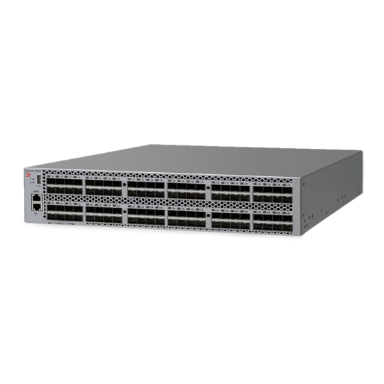
Real-time clock (RTC) with battery. Port side of the Brocade 6520 The port side of the Brocade 6520 includes the system status LED, console port, Ethernet port and LEDs, USB port, and Fibre Channel ports and the corresponding port status LEDs. -
Page 16: Non-Port Side Of The Brocade 6520
Port side view of the Brocade 6520 Non-port side of the Brocade 6520 Figure 2 shows the non-port side of the Brocade 6520, which contains the power supplies (including the AC power receptacle) and fans. Power supplies with integral fans... -
Page 17: Brocade 6520 Installation And Configuration
Brocade 6520 configuration........ -
Page 18: Installation And Safety Considerations
Brocade 6520 FRU, use correct ESD procedures. • Attach ground to the indicated area on the chassis. • Wear a wrist grounding strap connected to chassis ground (if the Brocade 6520 is plugged in) or a bench ground. • Store ESD-sensitive components in antistatic packaging. - Page 19 AC Measured 100 VAC 3.96 3.97 0.998 0.996 1343.8552 1347.266 120 VAC 3.26 3.29 0.997 0.995 1333.6228 1343.8552 200 VAC 1.94 2.02 0.997 0.963 1319.9796 1330.212 240 VAC 1.74 1.62 0.989 0.929 1313.158 1323.3904 Brocade 6520 Hardware Reference Manual 53-1002705-01...
-
Page 20: Environmental Considerations
A rack space that is two rack units (2U) high; 8.90 cm (3.50 inches) high and 48.3 cm (19 inches) wide. • There are three rack kit options that accommodate the Brocade 6520, a four-post fixed rack kit, a two-post Telco rack kit, and a four-post sliding rail rack kit. See their respective installation manuals for details. -
Page 21: Recommendations For Cable Management
• Use Velcro-style straps to secure and organize fiber-optic cables. Items required for installation The following items are required for installing, configuring, and connecting the Brocade 6520 for use in a network and fabric: • Workstation with an installed terminal emulator, such as HyperTerminal •... -
Page 22: Standalone Installation For A Brocade 6520
Brocade 6520 configuration Once you have set up the Brocade 6520 in a rack or as a standalone switch, it is time to give it power and a basic configuration. If you are going to use the Brocade 6520 in a single-switch setup, you can use EZSwitchSetup to complete the basic configuration. -
Page 23: Creating A Serial Connection
In a UNIX environment using TIP, enter the following string at the prompt: tip /dev/ttyb -9600 If ttyb is already in use, use ttya instead and enter the following string at the prompt: tip /dev/ttya -9600 Brocade 6520 Hardware Reference Manual 53-1002705-01... -
Page 24: Switch Ip Address
DHCP server. The DHCP client can only connect to a DHCP server that is on the same subnet as the switch. If your DHCP server is not on the same subnet as the Brocade 6520, use a static IP address. - Page 25 NTP server. The rest are stored as backup servers that can take over if the active NTP server fails. The principal or primary FCS switch synchronizes its time with the NTP server every 64 seconds. Brocade 6520 Hardware Reference Manual 53-1002705-01...
-
Page 26: Setting The Date And Time
Time Zone : US/Central The following procedure describes how to set the current time zone using interactive mode to Pacific Standard Time. 1. Enter the tsTimeZone command as follows: switch:admin> tstimezone --interactive Brocade 6520 Hardware Reference Manual 53-1002705-01... -
Page 27: Brocade Isl Trunking
6520 can be used as a trunking group to achieve speeds up to 128 Gbps (256 Gbps full duplex) for optimal bandwidth utilization and load balancing. For more information about Brocade ISL Trunking, refer to the Fabric OS Administrator’s Guide. Brocade 6520 Hardware Reference Manual 53-1002705-01... - Page 28 Brocade 6520 configuration Brocade 6520 Hardware Reference Manual 53-1002705-01...
-
Page 29: Brocade 6520 Operation
Brocade 6520 maintenance........ - Page 30 Ethernet port activity LED FC port status LED (port 0) Ethernet port speed LED FIGURE 3 LEDs on port side of Brocade 6520 Table 7 describes the port side LEDs and their behavior. TABLE 7 Port side LED patterns during normal operation...
- Page 31 Fast blinking green There is an internal loopback No action required. (1/2 sec) (diagnostic). Flickering green The port is online and frames No action required. are flowing through the port. Brocade 6520 Hardware Reference Manual 53-1002705-01...
- Page 32 Power supply DC status LED Fan status LED Power supply AC status LED FIGURE 4 LEDs on non-port side of Brocade 6520 Table 8 describes the LEDs on the non-port side of the switch. TABLE 8 Non-port side LED patterns during normal operation...
-
Page 33: Post And Boot-Up Specifications
Analyzes fabric. If any ports are connected to other switches, the switch participates in a fabric configuration. • Obtains a domain ID and assigns port addresses. • Constructs unicast routing tables. • Enables normal port operation. Brocade 6520 Hardware Reference Manual 53-1002705-01... -
Page 34: Interpreting Post Results
OS Administrator’s Guide. For information about error messages, refer to the Fabric OS Message Reference. Brocade 6520 maintenance The Brocade 6520 is designed for high availability and low failure; it does not require any regular physical maintenance. It includes diagnostic tests and field-replaceable units, described in the following sections. - Page 35 SFP+ transceiver into the upper row of ports is with the gold-plated edge down. The correct position to insert an SFP+ transceiver into the lower row of ports is with the gold-plated edge up. FIGURE 5 Installing a 16 Gbps SFP+ in the upper row of port slot Brocade 6520 Hardware Reference Manual 53-1002705-01...
-
Page 36: Diagnostic Tests
For information about specific diagnostic tests, refer to the Fabric OS Troubleshooting and Diagnostics Guide. Brocade 6520 management You can use the management functions built into the Brocade 6520 to monitor the fabric topology, port status, physical status, and other information to help you analyze switch performance and to accelerate system debugging. - Page 37 Brocade 6520 management For information about upgrading the version of Fabric OS installed on your switch, refer to the Fabric OS Administrator’s Guide. You can manage the Brocade 6520 using any of the management options listed in Table 9. Refer to the Fabric OS Command Reference for more information on the CLI commands.
- Page 38 Brocade 6520 management Brocade 6520 Hardware Reference Manual 53-1002705-01...
-
Page 39: Removal And Replacement Of Power Supplies And Fans
“Installation and safety considerations” before servicing. The field-replaceable units (FRUs) in the Brocade 6520 can be removed and replaced without special tools. The Brocade 6520 can continue operating during the FRU replacement if the conditions specified in the procedures are followed. -
Page 40: Power Supply Removal And Replacement
CRITICAL HIL-1611 MISMATCH in PSU/FAN Air Flow direction. Replace PSU with fan air flows in same direction. System will be shut down in 2 minutes. Power supply removal and replacement The Brocade 6520 has two power supplies, as displayed in Figure 2. The Fabric OS identifies the power supplies from left to right on the non-port side as power supply #2 and power supply #1. -
Page 41: Time And Items Required
Replacing a power supply in the Brocade 6520 should require less than two minutes to complete. To replace a power supply in a Brocade 6520 you need a new power supply that has the same part number and airflow indicator as the power supply being replaced. Refer to... -
Page 42: Replacing A Power Supply
Figure 9 this procedure. 1. To leave the Brocade 6520 in service while replacing a power supply, verify that the other power supply (the one not being replaced) has been powered on for at least four seconds and has a steady green status LED. -
Page 43: Fan Removal And Replacement
Fan removal and replacement FIGURE 9 Inserting the power supply in the Brocade 6520 6. Verify that the LEDs on the new power supply display steady green while the Brocade 6520 is operating (refer to Table 8). If the LEDs are not steady green, ensure that the power supply is securely installed and seated properly. -
Page 44: Determining The Need To Replace A Fan
Fan 5 is Ok, speed is 11995 RPM br6520:admin> Time and items required Replacing a fan in the Brocade 6520 should require less than two minutes to complete. You need the following items to replace a fan in the Brocade 6520: •... -
Page 45: Replacing A Brocade 6520 Fan
Captive screw FIGURE 10 Brocade 6520 fan Replacing a Brocade 6520 fan Complete the following steps to replace a fan in a Brocade 6520. Refer to Figure 11 for this procedure. 1. Using the Phillips screwdriver, unscrew the captive screw on the fan. - Page 46 Using the Phillips screwdriver, secure the fan to the chassis by tightening the captive screw. FIGURE 11 Inserting the fan in the Brocade 6520 4. Verify that the fan status LED is steady green to indicate normal operation (refer to Table Optionally, if using the command line interface (CLI), enter the fanShow command at the command line prompt to display the status.
-
Page 47: Sfp+ Transceiver Removal And Replacement
The extraction tool is designed to remove transceivers from modules where the space is limited. FIGURE 12 Optical transceiver extraction tool Removing an SFP+ transceiver For the following procedure refer to Figure 13 Figure Complete the following steps to remove an SFP+ transceiver. Brocade 6520 Hardware Reference Manual 53-1002705-01... -
Page 48: Replacing An Sfp+ Transceiver
Replacing an 8 Gbps or 10 Gbps SFP+ optical transceiver 16 Gbps SFP+ pull tab FIGURE 14 Replacing a 16 Gbps SFP+ optical transceiver Replacing an SFP+ transceiver For the following procedure refer to Figure 13 Figure Brocade 6520 Hardware Reference Manual 53-1002705-01... - Page 49 Insert the cable into the transceiver until the latching mechanism clicks. Cables are keyed so that they can be inserted in only one way. If a cable does not slide in easily, ensure that it is correctly oriented. Brocade 6520 Hardware Reference Manual 53-1002705-01...
- Page 50 SFP+ transceiver removal and replacement Brocade 6520 Hardware Reference Manual 53-1002705-01...
-
Page 51: Brocade 6520 Specifications
Environmental regulation compliance ......47 Weight and physical dimensions Table 10 lists the weight and physical dimensions of the Brocade 6520. TABLE 10 Physical specifications... -
Page 52: Data Transmission Ranges
10 km (6.2 mi.) SFP+ 16 Gbps 10 km (6.2 mi.) ELWL SFP+ 16 Gbps 25 km (15.5 mi.) Up to 7500 km at 2Gbps is supported when using a long distance transport system such as DWDM. Brocade 6520 Hardware Reference Manual 53-1002705-01... -
Page 53: Memory Specifications
The first eight ports on the switch can be configured to run at 10 Gbps with the appropriate license and transceivers. Serial port specifications The serial port is located on the port side of the switch. The Brocade 6520 uses an RJ45 connector for the serial port. An RJ45-to-RS-232 adapter is also provided with the switch. NOTE To protect the serial port from damage, keep the cover on the port when not in use. -
Page 54: Regulatory Compliance
Description UART1_RXD Receive data Not supported Not supported Regulatory compliance This section describes the regulatory compliance requirements for the Brocade 6520. It contains the following standards: • “FCC warning (US only)” on page 42 • “KCC statement (Republic of Korea)”... -
Page 55: Vcci Statement (Japan)
Information Technology Equipment (VCCI). If this equipment is used in a domestic environment, radio disturbance might arise. When such trouble occurs, the user might be required to take corrective actions. Power cords (Japan DENAN) Brocade 6520 Hardware Reference Manual 53-1002705-01... -
Page 56: China
Warning for Class A: English translation of above statement This is a Class A product. In a domestic environment this product may cause radio interference, i which case the user may be required to take adequate measures. Brocade 6520 Hardware Reference Manual 53-1002705-01... -
Page 57: Bsmi Statement (Taiwan)
FDA Class 1 radiation performance requirements defined in 21 CFR Subchapter I, and with IEC 825-2. Optical products that do not comply with these standards might emit light that is hazardous to the eyes. Brocade 6520 Hardware Reference Manual 53-1002705-01... -
Page 58: Electrical Cautions
IT power system. Regulatory certifications Table 15 lists the regulatory compliance standards for which the Brocade 6520 is certified. TABLE 15 Regulatory compliance standards Country... -
Page 59: Environmental Regulation Compliance
The EPUP assumes that the product will be used under normal conditions in accordance with the operating manual of the product. Brocade 6520 Hardware Reference Manual 53-1002705-01... - Page 60 Fibre Channel Switch Fan, Blower assemblies PCBA cards Power supply kit SFPs (SFP+ optical cable connectors) Sheet Metal Chassis Assembly Mechanical brackets and Slides Slot Filler Cable management tray Cable Comb Cables and power cords Brocade 6520 Hardware Reference Manual 53-1002705-01...
- Page 61 X indicates that the concentration of such hazardous/toxic substance in all the units of homogeneous material of such component is higher than the SJ/T11363-2006 Requirements for Concentration Limits. O indicates that no such substances are used or that the concentration is within the aforementioned limits. Brocade 6520 Hardware Reference Manual 53-1002705-01...
- Page 62 Environmental regulation compliance Brocade 6520 Hardware Reference Manual 53-1002705-01...
-
Page 63: Caution And Danger Notices
PRECAUCIÓN Use un circuito derivado separado para cada cordón de alimentación de CA, con lo que se proporcionará redundancia en caso de que uno de los circuitos falle. Brocade 6520 Hardware Reference Manual 53-1002705-01... -
Page 64: Danger Notices
Die Installation und Entfernung der Einheit dürfen nur von qualifiziertem Personal ausgeführt werden. DANGER L'installation et la dépose de l'unité doivent être confiées uniquement à du personnel qualifié. PELIGRO La instalación y desinstalación de la unidad debe llevarse a cabo solamente por personal cualificado. Brocade 6520 Hardware Reference Manual 53-1002705-01... - Page 65 Esta marca será su garantía de que el cordón de corriente puede ser utilizado con seguridad con el instrumento. Brocade 6520 Hardware Reference Manual 53-1002705-01...
- Page 66 Danger notices Brocade 6520 Hardware Reference Manual 53-1002705-01...
- Page 67 China class A statement determining fan status China RoHS determining status diagDisablePost command diagnostic port diagnostic tests DPOD Dynamic Path Selection, see DPS Dynamic Ports on Demand, see DPOD Brocade 6520 Hardware Reference Manual 53-1002705-01...
- Page 68 German acoustic statement system status local clock LOCL logging timestamp Brocade 6520 Hardware Reference Manual 53-1002705-01...
- Page 69 POST switch IP address psShow command static using DHCP switchShow synchronize local time using NTP system power LED rack considerations system status LED real time power monitoring real-time clock, see RTC Brocade 6520 Hardware Reference Manual 53-1002705-01...
- Page 70 USB port VCCI statement VF support Virtual Fabric, see VF wavelength support weight zoning Brocade 6520 Hardware Reference Manual 53-1002705-01...
Need help?
Do you have a question about the Brocade 6520 and is the answer not in the manual?
Questions and answers