Table of Contents
Advertisement
Quick Links
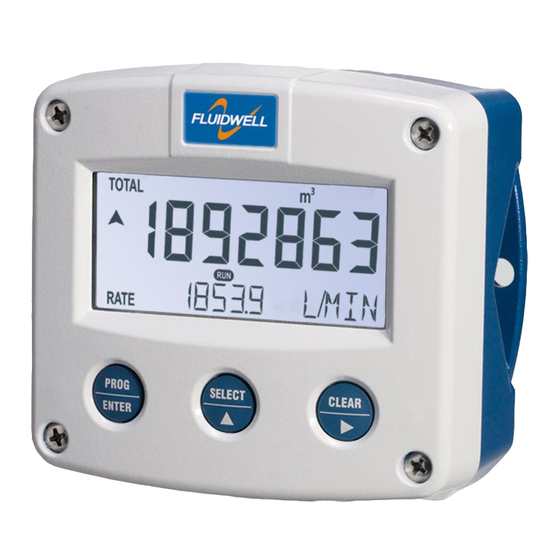
F112-P
FLOWRATE INDICATOR / TOTALIZER
WITH LINEARISATION
Signal input flowmeter: pulse, Namur and coil.
Signal outputs: (0)4-20mA / 0-10V ref. flowrate and pulse ref. total.
Options: Intrinsically Safe, Modbus communication, external reset and
backlight.
F-Series - Field mounted indicators for safe and hazardous areas. More info: www.fluidwell.com/fseries
Advertisement
Table of Contents

Related Manuals for Fluidwell F112-P


Summary of Contents for Fluidwell F112-P
- Page 1 Signal input flowmeter: pulse, Namur and coil. Signal outputs: (0)4-20mA / 0-10V ref. flowrate and pulse ref. total. Options: Intrinsically Safe, Modbus communication, external reset and backlight. F-Series - Field mounted indicators for safe and hazardous areas. More info: www.fluidwell.com/fseries...
-
Page 2: Safety Instructions
This unit must be installed in accordance with the EMC guidelines (Electro Magnetic Compatibility). Do connect a proper grounding to the aluminum casing as indicated if the F112-P has been supplied with the 115-230V AC power-supply type PM. The green / yellow wire between the back-casing and removable terminal-block may never be removed. -
Page 3: About The Operation Manual
This operation manual describes the standard unit as well as most of the options available. For additional information, please contact your supplier. A hazardous situation may occur if the F112-P is not used for the purpose it was designed for or is used incorrectly. Please carefully note the information in this operating manual indicated by the pictograms: A "warning"... -
Page 4: Table Of Contents
Disposal ..............................2 Safety rules and precautionary measures ....................... 2 About the operation manual ..........................3 Introduction ..........................5 1.1. System description of the F112-P ..................5 Operational ..........................7 2.1. General ..........................7 2.2. Control panel .......................... 7 2.3. -
Page 5: Introduction
SYSTEM DESCRIPTION OF THE F112-P Functions and features The flowrate / totalizer model F112-P is a microprocessor driven instrument designed to linearise the flowmeters flow curve and to display flowrate, total and accumulated total. This product has been designed with a focus on: ... - Page 6 Page 6 Configuration of the unit The F112-P was designed to be implemented in many types of applications. For that reason, a SETUP-level is available to configure your F112-P according to your specific requirements. SETUP includes several important features, such as K-factors, measurement units, signal selection etc.
-
Page 7: Operational
Take careful notice of the " Safety rules, instructions and precautionary measures " in the front of this manual. This chapter describes the daily use of the F112-P. This instruction is meant for users / operators. 2.2. CONTROL PANEL The following keys are available: Fig. -
Page 8: Operator Information And Functions
SETUP-settings. All pulses generated by the connected flowmeter are measured by the F112-P in the background, whichever screen refresh rate setting is chosen. After pressing a key, the display will be updated very quickly during a 30 second period, after which it will slow-down again. -
Page 9: Configuration
Operating Manual before carrying out its instructions. The F112-P may only be operated by personnel who are authorized and trained by the operator of the facility. All instructions in this manual are to be observed. - Page 10 Page 10 Matrix structure SETUP-level: SCROLLING THROUGH SETUP-LEVEL Selection of function-group and function: SETUP is divided into several function groups and functions. Each function has a unique number, which is displayed below the word "SETUP" at the bottom of the display. The number is a combination of two figures. The first figure indicates the function-group and the second figure the sub-function.
- Page 11 Page 11 To change or select a value: To change a value, use to select the digits and to increase that value. To select a setting, both and can be used. If the new value is invalid, the increase sign or decrease-sign will be displayed while you are programming.
-
Page 12: Overview Functions Setup Level
X,XXX,XXX quantity COMMUNICATION SPEED / BAUDRATE 1200 - 2400 - 4800 - 9600 ADDRESS 1 - 255 MODE rtu - off OTHERS TYPE / MODEL F112-P SOFTWARE VERSION SERIAL NO. PASS CODE 0000 - 9999 TAGNUMBER 0000000 - 9999999 HF112PEN_v0501_04... -
Page 13: Explanation Of Setup-Functions
Page 13 3.2.3. EXPLANATION OF SETUP-FUNCTIONS 1 - TOTAL SETUP - 11 determines the measurement unit for total, accumulated total MEASUREMENT UNIT and pulse output. The following units can be selected: L - m3 - kg - lb. - GAL - USGAL - bbl - _ (no unit). Alteration of the measurement unit will have consequences for operator and SETUP-level values. -
Page 14: Flowrate
Page 14 2 - FLOWRATE The settings for total and flowrate are entirely separate. In this way, different units of measurement can be used for each e.g. cubic meters for total and liters for flowrate. The display update time for flowrate is one second or more. Note: these settings also influence the analog output. -
Page 15: Display
When used with the internal battery option, the user can expect reliable measurement over a long period of time. The F112-P has several smart power management functions to extend the (optional) battery life time significantly. Two of these functions can be set:... -
Page 16: Flowmeter
Page 16 5 - FLOWMETER The F112-P is able to handle several types of input signal. The type of SIGNAL flowmeter pickup / signal is selected with SETUP 51. Note: The selections "active pulse" offer a detection level of 50% of the supply voltage. -
Page 17: Linearisation
Page 17 6 - LINEARISATION The linearization function is available to approach the real flow curve better as with the general K-factor (KF0) entered with setup 14 and 24. This to obtain a more accurate flowrate, total and accumulated total as well as the analog and pulse output at any flowmeter frequency. A maximum of 15 linearization-positions can be entered while the interpolation will calculate any other position in-between. -
Page 18: Analog Output
Page 18 7 - ANALOG OUTPUT A linear analog (0)4-20mA or 0-10V signal is generated according to the flowrate with a 10 bits resolution. The settings for flowrate (SETUP - 2) influence the analog output directly. The relationship between rate and analog output is set with the following functions: The analog output can be disabled. -
Page 19: Relay Output
Page 19 7 - ANALOG OUTPUT (CONTINUED) This function is used to stabilize the analog output signal. FILTER The output value is updated every 0.1 second. With the help of this digital filter a more stable but less precise reading can be obtained. The filter principal is based on three input values: the filter level (01-99), the last analog output value and the last average value. -
Page 20: Communication (Optional)
1200 - 2400 - 4800 - 9600 baud For communication purposes, a unique identity can be attributed to every BUS ADDRESS F112-P. This address can vary from 1-255. The communication protocol is Modbus RTU mode. Select OFF, to MODE disable this communication function. -
Page 21: Installation
Operating Manual before carrying out its instructions. The F112-P may only be operated by personnel who are authorized and trained by the operator of the facility. All instructions in this manual are to be observed. -
Page 22: Dimensions- Enclosure
Page 22 4.3. DIMENSIONS- ENCLOSURE Aluminum enclosures: 75 mm (2.95") 112 mm (4.40") 130 mm (5.12") 12mm 12mm 30mm 30mm 24mm 24mm M20 x 1,5 6 x M12 36mm 36mm 30mm 30mm M16 x 1,5 M16 x 1,5 1/2"NPT M20 x 1,5 0.12"... - Page 23 Page 23 GRP enclosures: 75 mm (2.95") 112 mm (4.40") 130 mm (5.12") HK back box: (flat bottom) 75 mm (2.95") 118 mm (4.65”) 25mm 25mm D=20mm D=20mm 12mm 12mm 30mm 30mm 24mm 24mm D=12mm D=16mm D=16mm D=20mm 36mm 36mm 0.12”...
-
Page 24: Installing The Hardware
Do ground the aluminum enclosure properly as indicated, if the F112-P has been supplied with the 115-230V AC power-supply type PM. The green / yellow wire between the back-casing and removable terminal-block may never be removed. -
Page 25: Voltage Selection Sensor Supply
Page 25 4.4.2. VOLTAGE SELECTION SENSOR SUPPLY For Intrinsically Safe applications: read chapter 5. Type PB / PC / PX (AP) - battery powered and output loop-powered applications: Terminal 11 provides a limited supply voltage of 3.2 V DC (coil signals 1.2V) for the signal output of the flowmeter. -
Page 26: Terminal Connectors
AI / AP / AU PULSE INPUT SIGNAL RESET Fig. 9: Overview of terminal connectors standard configuration F112-P and options. REMARKS: TERMINAL CONNECTORS: Terminal GND- 01- 02: Power Supply - only available with type PD / PF or PM: erminal... - Page 27 Page 27 Terminal 05-06; scaled pulse output R1: Setup 7 (par. 3.4.4.) determines the pulse output function. The maximum pulse frequency of this output is 60Hz. If a relay output option has been supplied, be sure that the output frequency does not exceed 5Hz or else the life-time of the relay will be reduced significantly.
- Page 28 Page 28 Terminal 07-08; basic POWER SUPPLY - type PX - output loop powered: Connect an external power supply of 8-30VDC to these terminals or a 4-20mA loop. Do connect the "-" to terminal 7 and the "+" to terminal 8. When power is applied to these terminals, the (optional) internal battery will be disabled / enabled automatically to extend the battery life time.
- Page 29 Page 29 Type AF: For the Intrinsically Safe floating 4-20mA signal: please read Chapter 5. Type AI: An isolated 4-20mA signal proportional to the flowrate is available with this option. When the output is disabled, a 3.5mA signal will be generated on these terminals. Max.
- Page 30 SETUP-function (read par. 3.2.3.) Sine-wave signal (Coil): The F112-P is suitable for use with flowmeters which have a coil output signal. Two sensitivity levels can be selected with the SETUP-function: COIL LO: sensitivity from about 120mVp-p.
- Page 31 Pulse-signal PNP / PNP-LP: The F112-P is suitable for use with flowmeters which have a PNP output signal. 3.2V is offered on terminal 11 which has to be switched by the sensor to terminal 10 (SIGNAL). For a reliable pulse detection, the pulse amplitude has to go above 1.2V.
- Page 32 REED LP - low-pass filter (read par. 3.2.3.) NAMUR-signal: The F112-P is suitable for flowmeters with an Namur signal. The standard F112-P is not able to power the Namur sensor, as an external power supply for the sensor is required. However, a 8.2V sensor supply voltage (terminal 11) can be provided with power supply type PD, PF, PM.
- Page 33 Page 33 Terminal 26-31: type CB / CH / CI / CT - communication RS232 / RS485 / TTL (option) Full serial communications and computer control in accordance with RS232 (length of cable max. 15 meters) or RS485 (length of cable max. 1200 meters) is possible. Read the Modbus communication protocol and Appendix C.
-
Page 34: Intrinsically Safe Applications
Please Note Certificates, safety values and declaration of compliance can be found in the document named: “Fluidwell F1..-..-XI - Documentation for Intrinsic Safety”. Special conditions for safe use mentioned in both the certificate and the installation instructions must be observed for the connection of power to both input and / or output circuits. -
Page 35: Terminal Connectors Intrinsically Safe Applications
Indicated labels on the back cover (below) and on the inside cover (right) show the type labels for intrinsically safe certified units. For details on usage see the separate “Fluidwell F1..-..-IX Documentation for Intrinsic Safety”. Serial number and year of production This information can be looked-up on the display: See setup function (par. - Page 36 Page 36 Explanation Intrinsically Safe options: Type AF - Intrinsically Safe floating 4-20mA analog output - Terminal 7-8: A floating 4-20mA signal proportional to the flowrate is available with this option. When the output is disabled, a 3.5mA signal will be generated. Max.
-
Page 37: Configuration Examples
Page 37 CONFIGURATION EXAMPLES Configuration example IIB - F112-P-AF-IB-CT-OT-(PB)-(PD)-XI HAZARDOUS AREA SAFE AREA TERMINAL CONNECTORS F100-series Modbus communication type CT: TTL I.S. Certified Isolator TTL to: = max. 30 V RS232 = max. 250 mA RS422 = max. 0.85 W e.g. - Page 38 Page 38 Configuration example IIB/IIIC and IIC - F112-P-AP-IB-(CT)-OT-PD-XI HAZARDOUS AREA SAFE AREA TERMINAL CONNECTORS F100-series Modbus communication type CT: TTL Please note: communciation type CT is allowed in IIC applications. I.S. Certified Isolator TTL to: = max. 30 V ...
-
Page 39: Battery Replacement Instructions
Batteries for use in safe areas have no Ex label. DO NOT EXCHANGE: Using the wrong type of battery can pose a SERIOUS RISK. For use in hazardous areas Fluidwell recommends FW-LiBAT batteries (manufactured by Fluidwell bv) only. Battery replacement procedure Depending on the production batch, one of two visualized Intrinsically Safe certified battery types may have been installed in the unit. -
Page 40: Maintenance
Operating Manual before carrying out its instructions. The F112-P may only be operated by personnel who are authorized and trained by the operator of the facility. All instructions in this manual are to be observed. -
Page 41: Appendix A: Technical Specification
Page 41 APPENDIX A: TECHNICAL SPECIFICATION GENERAL Display Type High intensity reflective numeric and alphanumeric LCD, UV-resistant. Digits Seven 17mm (0.67") and eleven 8mm (0.31"). Various symbols and measuring units. Refresh rate User definable: 8 times/sec - 30 secs. Type ZB Transflective LCD with green LED backlight. - Page 42 Page 42 Sensor excitation Type PB / PC / PX 3.2V DC for pulse signals and 1.2V DC for coil pick-up. Note: This is not a real sensor supply. Only suitable for pulse sensors with a very low power consumption like coils (sine wave) and reed-switches. Type PD 1.2 - 3.2 - 8.2 - 12 and 24V DC - max.
- Page 43 Page 43 OUTPUTS Analog output Function transmitting linearised flowrate. Accuracy 10 bit. Error < 0.05% - update 10 times a second. Software function to calibrate the 4.00mA and 20.00mA levels precisely within set-up. Load max. 1 kOhm Type AA Active 4-20mA output (requires type OA + PD, PF or PM). Type AB Active 0-20mA output (requires type OA + PD, PF or PM).
-
Page 44: Appendix B: Problem Solving
Page 44 APPENDIX B: PROBLEM SOLVING In this appendix, several problems are included that can occur when the F112-P is going to be installed or while it is in operation. Flowmeter does not generate pulses: Check: Signal selection SETUP - 51, ... -
Page 45: Appendix C: Communication Variables
Page 45 APPENDIX C: COMMUNICATION VARIABLES Remarks: Below, an overview of the F112-P specific variables; other common variables are described in the standard table. All numbers are decimal numbers, unless otherwise noted. The following variables of the standard table (var00-var30) are not valid for this product and will be responded with value 1: var00, 03-05, 07,08, 16-22, 24, 26-29. - Page 46 Page 46 DESCRIPTION BYTES VALUE REMARKS DISPLAY display function 0=total (40h) 1=flowrate set flowrate monitor 0=operator level (44h) 1=SETUP level POWERMANAGEMENT LCD update time 0=fast (50h) 1=1sec 2=3sec 3=15sec 4=30sec 5=off power-mode battery 1 0=operational (51h) 1=shelf FLOWMETER flowmeter signal 0=npn (60h) 1=npn-lp...
- Page 47 REMARKS tagnumber 0..9999999 Other vars: see standard table OTHER F112-P VARIABLES FOR COMMUNICATION TOTAL - variable number 566 (236h) – 6 bytes Read total: The value of total read using RS communications might differ from the value that appears on the display. This is due to the fact that the display can only display up to...
-
Page 48: Notes
Page 48 NOTES HF112PEN_v0501_04... - Page 49 Page 49 Left blank intentionally HF112PEN_v0501_04...
-
Page 50: Index Of This Manual
Fig. 7: Grounding aluminum enclosure with type PM 115-230V AC..........24 Fig. 8: Switch setting sensor supply voltage..................25 Fig. 9: Overview of terminal connectors standard configuration F112-P and options......26 Fig. 10: Overview terminal connectors communication option............33 Fig. - Page 51 Page 51 LIST OF CONFIGURATION SETTINGS SETTING DEFAULT DATE : DATE : 1 - TOTAL Enter your settings here 11 unit 12 decimals 0000000 13 K-factor 0000001 14 decimals K-factor 2 - FLOWRATE 21 unit 22 time unit /min 23 decimals 0000000 24 K-factor 0000001...
- Page 52 A3 serial number A4 pass code 0000 A5 tagnumber 0000000 Fluidwell bv HF112PEN_v0501_04 PO box 6 Voltaweg 23 Website: www.fluidwell.com 5460 AA Veghel 5466 AZ Veghel Find your nearest representative: www.fluidwell.com/representatives The Netherlands The Netherlands Copyright Fluidwell bv - 2012 - HF110AEN_v0501_03...
Need help?
Do you have a question about the F112-P and is the answer not in the manual?
Questions and answers