Sign In
Upload
Download
Add to my manuals
Delete from my manuals
Share
URL of this page:
HTML Link:
Bookmark this page
Add
Manual will be automatically added to "My Manuals"
Print this page
×
Bookmark added
×
Added to my manuals
Manuals
Brands
KDK Manuals
Fan
M56RG
Operating and instalation instructions
KDK M56RG Operating And Instalation Instructions
Hide thumbs
1
2
3
4
5
6
7
8
9
10
11
12
page
of
12
Go
/
12
Contents
Table of Contents
Bookmarks
Advertisement
Quick Links
1
Maintenance
2
M56Rg N56Rg
3
Product Specifi Cation
Download this manual
Operating And Installation Instructions
Thank you for purchasing KDK Ceiling Fan.
Before operating this product, please read the instructions carefully, and keep this manual
for future reference.
Contents
Safety Precautions
Supplied Parts
How To Assemble
How To Use
Maintenance
Product Specifi cation
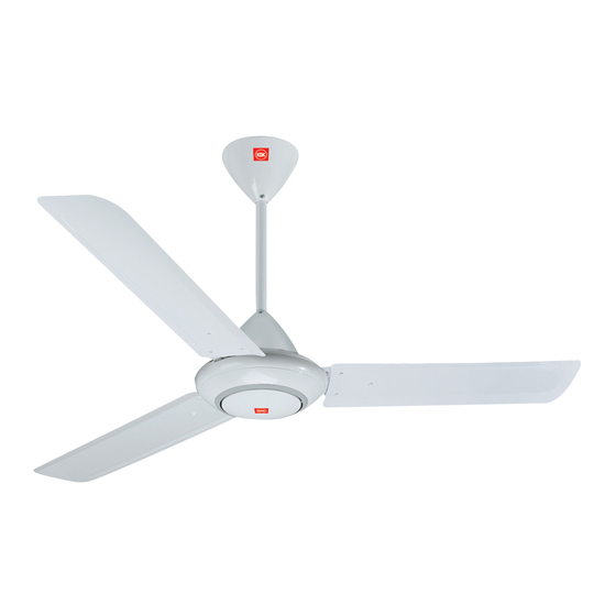
Ceiling Fan
Model Number
M56RG
N56RG
Page
2
4
4
12
12
12
Previous
Page
Next
Page
1
2
3
4
5
Advertisement
Need help?
Do you have a question about the M56RG and is the answer not in the manual?
Ask a question
Questions and answers
Related Manuals for KDK M56RG
Fan KDK M56XG Operating And Installation Instructions
(17 pages)
Fan KDK M56XG Operating And Installation Instructions
(16 pages)
Fan KDK M56XG Operating And Installation Instructions
(16 pages)
Fan KDK M56SR Operating And Installation Instructions
(16 pages)
Fan KDK M56PR Operating And Installation Instructions
(16 pages)
Fan KDK M56XR Operating And Installation Instructions
(16 pages)
Fan KDK M56QR Operating And Installation Instructions
(16 pages)
Fan KDK M48SG Operating And Installation Instructions
(16 pages)
Fan KDK M48SG Operating And Installation Instructions
(16 pages)
Fan KDK M40CH Operating Instructions Manual
Electric fan (9 pages)
Fan KDK M35CH Operating Instructions Manual
Electric fan (9 pages)
Fan KDK M30CH Operating Instructions Manual
Electric fan (9 pages)
Fan KDK M40CS Operating Instructions Manual
Electric fan (9 pages)
Fan KDK M11SU Operating And Installation Instructions
(15 pages)
Fan KDK M11SU Operating And Installation Instructions
(7 pages)
Fan KDK M48WG Operating And Installation Instructions
(16 pages)
This manual is also suitable for:
N56rg
Print
Rename the bookmark
Delete bookmark?
Delete from my manuals?
Login
Sign In
OR
Sign in with Facebook
Sign in with Google
Upload manual
Upload from disk
Upload from URL


Need help?
Do you have a question about the M56RG and is the answer not in the manual?
Questions and answers