
Related Manuals for YASKAWA VIPA SLIO FM 050


Summary of Contents for YASKAWA VIPA SLIO FM 050
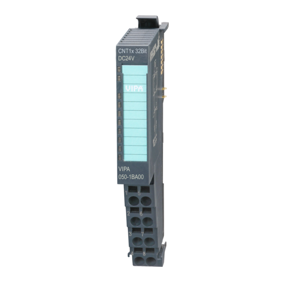
- Page 1 VIPA System SLIO FM 050 FM | 050-1BB40 | Manual HB300 | FM | 050-1BB40 | GB | 15-11...
- Page 2 VIPA GmbH Ohmstr. 4 91074 Herzogenaurach Telephone: 09132-744-0 Fax: 09132-744-1864 Email: info@vipa.com Internet: www.vipa.com 050-1BB40_000_FM050,4,GB - © 2015...
-
Page 3: Table Of Contents
VIPA System SLIO FM 050 Table of contents Table of contents General..................4 1.1 Copyright © VIPA GmbH ........... 4 1.2 About this manual.............. 5 1.3 Safety information.............. 6 Basics and Assembly.............. 8 2.1 Safety information for users..........8 2.2 System conception............. 9 2.3 Dimensions.............. -
Page 4: General
General VIPA System SLIO FM 050 Copyright © VIPA GmbH General 1.1 Copyright © VIPA GmbH All Rights Reserved This document contains proprietary information of VIPA and is not to be disclosed or used except in accordance with applicable agree- ments. -
Page 5: About This Manual
VIPA System SLIO FM 050 General About this manual Trademarks VIPA, SLIO, System 100V, System 200V, System 300V, System 300S, System 400V, System 500S and Commander Compact are registered trademarks of VIPA Gesellschaft für Visualisierung und Prozessautomatisierung mbH. SPEED7 is a registered trademark of profichip GmbH. SIMATIC, STEP, SINEC, TIA Portal, S7-300 and S7-400 are regis- tered trademarks of Siemens AG. -
Page 6: Safety Information
General VIPA System SLIO FM 050 Safety information Guide to the document The following guides are available in the manual: An overall table of contents at the beginning of the manual References with page numbers Availability The manual is available in: printed form, on paper in electronic form as PDF-file (Adobe Acrobat Reader) Icons Headings... - Page 7 VIPA System SLIO FM 050 General Safety information CAUTION! The following conditions must be met before using or commissioning the components described in this manual: – Hardware modifications to the process control system should only be carried out when the system has been disconnected from power! –...
-
Page 8: Basics And Assembly
Basics and Assembly VIPA System SLIO FM 050 Safety information for users Basics and Assembly 2.1 Safety information for users Handling of electro- VIPA modules make use of highly integrated components in MOS- static sensitive modules Technology. These components are extremely sensitive to over-vol- tages that can occur during electrostatic discharges. -
Page 9: System Conception
VIPA System SLIO FM 050 Basics and Assembly System conception 2.2 System conception Overview System SLIO is a modular automation system for assembly on a 35mm mounting rail. By means of the peripheral modules with 2, 4 or 8 channels this system may properly be adapted matching to your automation tasks. - Page 10 Basics and Assembly VIPA System SLIO FM 050 System conception With a CPU, CPU electronic and power module are integrated to one casing. As head module via the integrated power module for power supply the CPU electronic is supplied as well as the electronic of the connected periphery modules.
- Page 11 VIPA System SLIO FM 050 Basics and Assembly System conception Terminal module The terminal module serves to carry the electronic module, contains the backplane bus with power supply for the electronic, the DC 24V power section supply and the staircase-shaped terminal for wiring. Additionally the terminal module has a locking system for fixing at a mounting rail.
- Page 12 Basics and Assembly VIPA System SLIO FM 050 System conception (1) DC 24V for power section supply I/O area (max. 10A) (2) DC 24V for electronic power supply bus coupler and I/O area (3) DC 24V for power section supply I/O area (max. 4A) (4) DC 24V for electronic power supply I/O area Accessories Shield bus carrier...
-
Page 13: Dimensions
VIPA System SLIO FM 050 Basics and Assembly Dimensions Bus cover With each bus coupler, to protect the backplane bus connectors, there is a mounted bus cover in the scope of delivery. You have to remove the bus cover of the bus coupler before mounting a SLIO module. - Page 14 Basics and Assembly VIPA System SLIO FM 050 Dimensions Dimensions bus cou- pler Dimensions periphery module Dimensions electronic module Dimensions in mm HB300 | FM | 050-1BB40 | GB | 15-11...
-
Page 15: Installation
VIPA System SLIO FM 050 Basics and Assembly Installation 2.4 Installation Functional principle There is a locking lever at the top side of the terminal module. For mounting and demounting this locking lever is to be turned upwards until this engages audible. Now the module may be pulled forward. For mounting plug the module to the module installed before and push the module to the mounting rail guided by the strips at the upper and lower side of the module. - Page 16 Basics and Assembly VIPA System SLIO FM 050 Installation Each electronic module has on its back 2 coding sockets for coding jacks. Due to the characteristics, with the coding jack 6 different posi- tions can be plugged, each. Thus there are 36 possible combinations for coding with the use of both coding sockets.
- Page 17 VIPA System SLIO FM 050 Basics and Assembly Installation Mounting rail Mount the mounting rail! Please consider that a clearance from the middle of the mounting rail of at least 80mm above and 60mm below, respectively 80mm by deployment of shield bus carriers, exist.
- Page 18 Basics and Assembly VIPA System SLIO FM 050 Installation Mounting periphery modules Mount the periphery modules you want. Mounting the bus cover After mounting the whole system, to protect the backplane bus connectors at the last module you have to mount the bus cover, now.
-
Page 19: Demounting And Module Exchange
VIPA System SLIO FM 050 Basics and Assembly Demounting and module exchange Mounting shield bus carrier The shield bus carrier (available as accessory) serves to carry the shield bus to connect cable shields. The shield bus carrier is mounted underneath the terminal of the terminal module. With a flat mounting rail for adaption to a flat mounting rail you may remove the spacer of the shield bus carrier. - Page 20 Basics and Assembly VIPA System SLIO FM 050 Demounting and module exchange Exchange of a module Ä Chapter 2.6 ‘Wiring’ on page 23. Remove if exists the wiring. Press the unlocking lever at the lower side of the just mounted right module and pull it forward.
- Page 21 VIPA System SLIO FM 050 Basics and Assembly Demounting and module exchange CAUTION! Bus interface and power module of a head module may not be separated! Here you may only exchange the electronic module! Remove if exists the wiring of the head module. Ä...
- Page 22 Basics and Assembly VIPA System SLIO FM 050 Demounting and module exchange Exchange of a module group Ä Chapter 2.6 Remove if exists the wiring of the module group. ‘Wiring’ on page 23. Press the unlocking lever at the lower side of the just mounted right module of the module group and pull it forward.
-
Page 23: Wiring
VIPA System SLIO FM 050 Basics and Assembly Wiring Turn all the locking lever downward again. Plug again the electronic module, which you have removed before. 2.6 Wiring Connectors Terminals with spring clamp technology are used for wiring. The spring clamp technology allows quick and easy connection of your signal and supply lines. - Page 24 Basics and Assembly VIPA System SLIO FM 050 Wiring Standard wiring (1) DC 24V for power section supply I/O area (max 10A) (2) DC 24V for electronic power supply bus coupler and I/O area PM - Power module For wires with a core cross-section of 0.08mm up to 1.5mm Pos.
- Page 25 VIPA System SLIO FM 050 Basics and Assembly Wiring The electronic power section supply is internally protected against higher voltage by fuse. The fuse is within the power module. If the fuse releases, its electronic module must be exchanged! Fusing The power section supply is to be externally protected with a fuse, which corresponds to the maximum current.
- Page 26 Basics and Assembly VIPA System SLIO FM 050 Wiring Power module 007-1AB10 (1) DC 24V for power section supply I/O area (max. 10A) (2) DC 24V for electronic power supply bus coupler and I/O area (3) DC 24V for power section supply I/O area (max. 4A) (4) DC 24V for electronic power supply I/O area Shield attachment To attach the shield the mounting of shield bus carriers are neces-...
-
Page 27: Trouble Shooting - Leds
VIPA System SLIO FM 050 Basics and Assembly Installation guidelines 2.7 Trouble shooting - LEDs General Each module has the LEDs RUN and MF on its front side. Errors or incorrect modules may be located by means of these LEDs. In the following illustrations flashing LEDs are marked by ☼. - Page 28 Basics and Assembly VIPA System SLIO FM 050 Installation guidelines What does EMC mean? Electromagnetic compatibility (EMC) means the ability of an electrical device, to function error free in an electromagnetic environment without being interfered respectively without interfering the environ- ment.
- Page 29 VIPA System SLIO FM 050 Basics and Assembly Installation guidelines In special use cases you should appoint special EMC actions. – Consider to wire all inductivities with erase links. – Please consider luminescent lamps can influence signal lines. Create a homogeneous reference potential and ground all elec- trical operating supplies when possible.
-
Page 30: General Data
Basics and Assembly VIPA System SLIO FM 050 General data 2.9 General data Conformity and approval Conformity 2006/95/EG Low-voltage directive 2004/108/EG EMC directive Approval UL 508 Approval for USA and Canada others RoHS 2011/65/EU Product is lead-free; Restriction of the use of certain hazardous substances in electrical and electronic equipment Protection of persons and device protection... - Page 31 VIPA System SLIO FM 050 Basics and Assembly General data Mounting conditions Mounting place In the control cabinet Mounting position Horizontal and vertical Standard Comment Emitted interfer- EN 61000-6-4 Class A (Industrial area) ence Noise immunity EN 61000-6-2 Industrial area zone B EN 61000-4-2 8kV at air discharge (degree of severity 3),...
-
Page 32: Hardware Description
Hardware description VIPA System SLIO FM 050 Properties Hardware description 3.1 Properties Features Frequency measurement module 2 channels 24bit, DC 24V Input frequency max. 600kHz (rising edge) Evaluation of period duration in 1µs, range 1µs ... 8s Evaluation of frequency in mHz, range 60mHz ... 600kHz Evaluation of speed in rpm Input filter (configurable) Order data... -
Page 33: Structure
VIPA System SLIO FM 050 Hardware description Structure 3.2 Structure 050-1BB40 1 Locking lever terminal module 2 Labeling strip 3 Backplane bus 4 LED status indication 5 DC 24V power section supply 6 Electronic module 7 Terminal module 8 Locking lever electronic module 9 Terminal Status indication Description... -
Page 34: Technical Data
Hardware description VIPA System SLIO FM 050 Technical data Pin assignment For wires with a cross section of 0.08mm up to 1.5mm Pos. Function Type Description not connected. DC 24V DC 24V for encoder not connected. Channel 0: pulse input DC 24V DC 24V for encoder Channel 1: pulse input... - Page 35 VIPA System SLIO FM 050 Hardware description Technical data Order no. 050-1BB40 Reverse polarity protection of rated load voltage Current consumption from load voltage L+ 5 mA (without load) Rated value DC 20.4...28.8 V Input voltage for signal "0" DC 0...5 V Input voltage for signal "1"...
- Page 36 Hardware description VIPA System SLIO FM 050 Technical data Order no. 050-1BB40 Switching frequency on lamp load Internal limitation of inductive shut-off voltage Short-circuit protection of output Trigger level Number of operating cycle of relay outputs Switching capacity of contacts Output data size 12 Byte Technical data counters...
- Page 37 VIPA System SLIO FM 050 Hardware description Technical data Order no. 050-1BB40 Max. potential difference between circuits Max. potential difference between inputs (Ucm) - Max. potential difference between Mana and Mintern (Uiso) Max. potential difference between inputs and Mana (Ucm) Max.
-
Page 38: Deployment
Deployment VIPA System SLIO FM 050 Fast introduction Deployment 4.1 Fast introduction Frequency range Limits Value Lower frequency limit 60mHz Upper frequency limit 600kHz Min. pulse time 800ns Min. pause time 800ns Address areas Input area At CPU, PROFIBUS and PROFINET the input respectively output area is embedded to the corresponding address area. - Page 39 VIPA System SLIO FM 050 Deployment Fast introduction Output area At CPU, PROFIBUS and PROFINET the output area is embedded to the corresponding address area. IX - Index for access via CANopen SX - Subindex (7000h + EtherCAT-Slot) for access via EtherCAT More can be found in the according manual of your bus coupler.
-
Page 40: Principle Of Operation
Deployment VIPA System SLIO FM 050 Principle of operation Frequency measure- With the following VIPA specific functions, you can control the system ment via VIPA specific SLIO frequency measurement module: functions Function Symbol Comment FC 300 FM_SET_CONTROL Function to control the frequency measurement with integrated consistent access. -
Page 41: In-/Output Area
VIPA System SLIO FM 050 Deployment In-/Output area > Input area 20byte Measurement active: FM_CONTROL_CH0: CTRL_FM_START = 1: Measurement is started FM_CONTROL_CH0: CTRL_FM_STOP = 1: Measurement is stopped Measurement period (here 200µs), preset via FM_PRESET_PERIOD_CH0 (PP_0). Signal to be measured, which is connected to channel 0. The 1. -
Page 42: Output Area 12Byte
Deployment VIPA System SLIO FM 050 In-/Output area > Output area 12byte Addr. Name Bytes Function FM_STATUS_CH0 Channel 0: 5462h/s status FM_STATUS_CH1 Channel 1: 5462h/s+1 status FM_PERIOD_ CHx The measured time value is the time between the last rising edge of Period duration the previous measuring period and the last rising edge of the current measuring period. -
Page 43: Determining The Magnitude Of The Measurement Period
VIPA System SLIO FM 050 Deployment In-/Output area > Determining the magnitude of the measurement period FM_CONTROL_ CHx Name Function Control word 7 ... 0 reserved CTRL_FM_START Start frequency measurement CTRL_FM_STOP Stop frequency measurement 15 ... 10 - reserved 4.3.3 Determining the magnitude of the measurement period The frequency measurement module measures the time between the last rising edge of the previous measurement period and the last rising edge of the current measurement period and counts rising... -
Page 44: Parameter Data
Deployment VIPA System SLIO FM 050 VIPA specific blocks > Include VIPA library 4.4 Parameter data DS - Record set for access via CPU, PROFIBUS and PROFINET IX - Index for access via CANopen SX - Subindex (3100h + EtherCAT-Slot) for access via EtherCAT More can be found in the according manual of your bus coupler. -
Page 45: Fc 300
VIPA System SLIO FM 050 Deployment VIPA specific blocks > FC 300 ... 303 Retrieve library To retrieve your library for the SPEED7-CPUs, start the SIMATIC manager from Siemens. Open the dialog window for archive selection via ‘File è Retrieve’. Navigate to your work directory. - Page 46 Deployment VIPA System SLIO FM 050 VIPA specific blocks > FC 300 ... 303 4.5.2.1.1 Parameters Parameter Declaration Data type Memory block Description ENABLE_FM INPUT BOOL I, Q, M, D, L Enable frequency measurement LADDR_OUT INPUT WORD I, Q, M, D, L Logical base address PRESET_CH0 INPUT...
- Page 47 VIPA System SLIO FM 050 Deployment VIPA specific blocks > FC 300 ... 303 Code Description 0x80D4 Channel 0: Input value measurement period > 8 388 607µs 0x80D5 Channel 1: Input value measurement period > 8 388 607µs 4.5.2.1.2 Errors of the internally called SFC 15 Code Description 0x808x...
- Page 48 Deployment VIPA System SLIO FM 050 VIPA specific blocks > FC 300 ... 303 4.5.2.2.1 Parameters Parameter Declaration Data type Memory block Description LADDR_IN INPUT WORD I, Q, M, D, L Logical base input address DONE OUTPUT BOOL I, Q, M, D, L Ready signal (TRUE = OK) ERROR OUTPUT...
- Page 49 VIPA System SLIO FM 050 Deployment VIPA specific blocks > FC 300 ... 303 4.5.2.2.2 Error of the internal called SFC 14 Code Description 0x808x System error on the bus coupler 0x8090 LADDR_IN is not correct, possible reasons: there is no module configured on this address limitation of the length of consistent data was not considered Basic address in parameter LADDR_IN...
- Page 50 Deployment VIPA System SLIO FM 050 VIPA specific blocks > FC 300 ... 303 Parameter Declaration Data type Memory block Description ERROR OUTPUT WORD I, Q, M, D, L Return value (0 = OK) FREQUENCY_CH0 OUTPUT DINT I, Q, M, D, L Channel 0: Frequency FREQUENCY_CH1 OUTPUT...
- Page 51 VIPA System SLIO FM 050 Deployment VIPA specific blocks > FC 300 ... 303 4.5.2.3.2 Error of the internal called SFC 14 Code Description 0x808x System error on the bus coupler 0x8090 LADDR_IN is not correct, possible reasons: there is no module configured on this address limitation of the length of consistent data was not considered Basic address in parameter LADDR_IN...
- Page 52 Deployment VIPA System SLIO FM 050 VIPA specific blocks > FC 300 ... 303 4.5.2.4.1 Parameters Parameter Declaration Data type Memory block Description LADDR_IN INPUT WORD I, Q, M, D, L Logical base input address RESOLUTION_CH0 INPUT DINT I, Q, M, D, L Channel 0: Resolution of the sensor RESOLUTION_CH1 INPUT...
- Page 53 VIPA System SLIO FM 050 Deployment VIPA specific blocks > FC 300 ... 303 Code Description 0x80D8 Channel 0: Input value RESOLUTION_CH0 < 0 0x80D9 Channel 1: Input value RESOLUTION_CH1 < 0 0x80DA Channel 0: Measured time value = 0 0x80DB Channel 1: Measured time value = 0 0x80DC...
-
Page 54: Fc 310
Deployment VIPA System SLIO FM 050 VIPA specific blocks > FC 310 ... 313 Code Description 0x80C1 The data from the previous write request on the module are not processed by the module, yet. 0x80C2 System error on the bus coupler 0x80Fx System error on the bus coupler 0x85xy... - Page 55 VIPA System SLIO FM 050 Deployment VIPA specific blocks > FC 310 ... 313 4.5.3.1.1 Parameters Parameter Declara- Data type Memory Description tion block ENABLE_FM INPUT BOOL I, Q, M, D, L Enable frequency measurement PRESET_CH0 INPUT DINT I, Q, M, D, L Channel 0: Measurement period PRESET_CH1...
- Page 56 Deployment VIPA System SLIO FM 050 VIPA specific blocks > FC 310 ... 313 DONE Ready signal of the function TRUE: Function was finished without error. FALSE: Function is not active respectively there is an error. FM_PRESET_ This parameter contains the measuring period for channel 0 respec- PERIOD_CHx tively channel 1.
- Page 57 VIPA System SLIO FM 050 Deployment VIPA specific blocks > FC 310 ... 313 4.5.3.2.1 Parameters Parameter Declara- Data Memory Description tion type block FM_PERIOD_CH0 INPUT DWORD I, Q, M, D, L Actual value of frequency measurement module input address: FM_PERIOD_CH1 INPUT DWORD...
- Page 58 Deployment VIPA System SLIO FM 050 VIPA specific blocks > FC 310 ... 313 FM_STATUS_CHx This parameter contains the status of channel 0 respectively channel 1. The content is to be consistent connected with address +16 respectively +18 of the input area of the frequency measurement module, via the according bus system.
- Page 59 VIPA System SLIO FM 050 Deployment VIPA specific blocks > FC 310 ... 313 4.5.3.3.1 Parameters Parameter Declara- Data Memory Description tion type block FM_PERIOD_CH0 INPUT DWORD I, Q, M, D, L Actual value of frequency measurement module input address: FM_PERIOD_CH1 INPUT DWORD...
- Page 60 Deployment VIPA System SLIO FM 050 VIPA specific blocks > FC 310 ... 313 FM_STATUS_CHx This parameter contains the status of channel 0 respectively channel 1. The content is to be consistent connected with address +16 respectively +18 of the input area of the frequency measurement module, via the according bus system.
- Page 61 VIPA System SLIO FM 050 Deployment VIPA specific blocks > FC 310 ... 313 4.5.3.4.1 Parameters Parameter Declara- Data Memory Description tion type block FM_PERIOD_CH0 INPUT DWORD I, Q, M, D, L Actual value of frequency measurement module input address: +0 FM_PERIOD_CH1 INPUT DWORD...
- Page 62 Deployment VIPA System SLIO FM 050 VIPA specific blocks > FC 310 ... 313 FM_RISING_ This parameter contains the determined number of rising edges for EDGES_CHx channel 0 respectively channel 1. The content is to be consistent con- nected with address +8 respectively +12 of the input area of the fre- quency measurement module, via the according bus system.
-
Page 63: Diagnostic Data
VIPA System SLIO FM 050 Deployment Diagnostic data Code Description 0x80E7 Channel 1: Determined rotational speed > max (DINT) 0x80E8 Channel 0: No valid measurement within the entered measurement period. 0x80E9 Channel 1: No valid measurement within the entered measurement period. 4.6 Diagnostic data Overview So this module does not support process interrupts, the diagnostics... - Page 64 Deployment VIPA System SLIO FM 050 Diagnostic data CHTYP Channel type Byte Bit 7 ... 0 Bit 6 ... 0: Channel type – 76h: Counter module Bit 7: reserved NUMBIT Diagnostic bits Byte Bit 7 ... 0 Number of diagnostics bits of the module per channel (here 00h) NUMCH Channels Byte...
Need help?
Do you have a question about the VIPA SLIO FM 050 and is the answer not in the manual?
Questions and answers