Table of Contents
Advertisement
Quick Links
Advertisement
Table of Contents

Related Manuals for YASKAWA VIPA IM 053IP


Summary of Contents for YASKAWA VIPA IM 053IP
- Page 1 VIPA System SLIO IM | 053-1IP00 | Manual HB300 | IM | 053-1IP00 | GB | 13-50...
- Page 2 VIPA GmbH Ohmstr. 4 91074 Herzogenaurach Telephone: +49 9132-744-0 Fax: +49 9132-744-1864 email: info@vipa.com Internet: www.vipa.com 053-1IP00_000_IM 053IP,2,GB - © 2013...
-
Page 3: Table Of Contents
VIPA System SLIO Table of contents Table of contents General..................4 1.1 Copyright © VIPA GmbH ........... 4 1.2 About this manual.............. 5 1.2.1 Safety information............6 Basics and Assembly.............. 8 2.1 Safety Information for Users..........8 2.2 System conception............. 9 2.3 Dimensions.............. -
Page 4: General
General VIPA System SLIO Copyright © VIPA GmbH General 1.1 Copyright © VIPA GmbH All Rights Reserved This document contains proprietary information of VIPA and is not to be disclosed or used except in accordance with applicable agree- ments. This material is protected by the copyright laws. It may not be repro- duced, distributed, or altered in any fashion by any entity (either internal or external to VIPA), except in accordance with applicable agreements, contracts or licensing, without the express written con-... -
Page 5: About This Manual
VIPA System SLIO General About this manual Trademarks VIPA, SLIO, System 100V, System 200V, System 300V, System 300S, System 400V, System 500S and Commander Compact are registered trademarks of VIPA Gesellschaft für Visualisierung und Prozessautomatisierung mbH. SPEED7 is a registered trademark of profichip GmbH. SIMATIC, STEP, SINEC, TIA Portal, S7-300 and S7-400 are regis- tered trademarks of Siemens AG. -
Page 6: Safety Information
General VIPA System SLIO About this manual> Safety information Guide to the document The following guides are available in the manual: An overall table of contents at the beginning of the manual References with page numbers Availability The manual is available in: printed form, on paper in electronic form as PDF-file (Adobe Acrobat Reader) Icons Headings... - Page 7 VIPA System SLIO General About this manual > Safety information CAUTION! The following conditions must be met before using or commissioning the components described in this manual: – Hardware modifications to the process control system should only be carried out when the system has been disconnected from power! –...
-
Page 8: Basics And Assembly
Basics and Assembly VIPA System SLIO Safety Information for Users Basics and Assembly 2.1 Safety Information for Users Handling of electro- VIPA modules make use of highly integrated components in MOS- static sensitive modules Technology. These components are extremely sensitive to over-vol- tages that can occur during electrostatic discharges. -
Page 9: System Conception
VIPA System SLIO Basics and Assembly System conception 2.2 System conception Overview System SLIO is a modular automation system for assembly on a 35mm mounting rail. By means of the peripheral modules with 2, 4 or 8 channels this system may properly be adapted matching to your automation tasks. - Page 10 Basics and Assembly VIPA System SLIO System conception Bus coupler With a bus coupler bus interface and power module are integrated to one casing. With the bus interface you get access to a subordinated bus system. As head module via the integrated power module for power supply the bus interface is supplied as well as the electronic of the connected periphery modules.
- Page 11 VIPA System SLIO Basics and Assembly System conception Electronic module The functionality of a SLIO periphery module is defined by the elec- tronic module, which is mounted to the terminal module by a safe sliding mechanism. With an error the defective module may be exchanged for a functional module with standing installation.
-
Page 12: Dimensions
Basics and Assembly VIPA System SLIO Dimensions Coding pins There is the possibility to fix the assignment of electronic and terminal module. Here coding pins (order number 000-0AC00) from VIPA can be used. The coding pin consists of a coding jack and a coding plug. By com- bining electronic and terminal module with coding pin, the coding jack remains in the electronic module and the coding plug in the terminal module. -
Page 13: Installation
VIPA System SLIO Basics and Assembly Installation Dimensions periphery module Dimensions electronic module Dimensions in mm 2.4 Installation Functional principle There is a locking lever at the top side of the terminal module. For mounting and demounting this locking lever is to be turned upwards until this engages audible. - Page 14 Basics and Assembly VIPA System SLIO Installation For the exchange of a electronic module, the electronic module may be pulled forward after pressing the unlocking lever at the lower side of the module. For installation plug the electronic module guided by the strips at the lower side until this engages audible to the terminal module.
- Page 15 VIPA System SLIO Basics and Assembly Installation CAUTION! Please consider that when replacing an already coded electronic module, this is always be replaced by an elec- tronic module with the same coding. Even with an existing coding on the terminal module, you can plug an electronic module without coding.
- Page 16 Basics and Assembly VIPA System SLIO Installation Mounting Head module (e.g. bus coupler) Start at the left side with the head module (e.g. bus coupler). For this turn both locking lever upwards, put the head module to the mounting rail and turn both locking lever downward. Before mounting the periphery modules you have to remove the bus cover at the right side of the Head module by pulling it for- ward.
- Page 17 VIPA System SLIO Basics and Assembly Installation Mounting the bus cover After mounting the whole system, to protect the backplane bus connectors at the last module you have to mount the bus cover, now. Mounting the bus cover at a clamp module If the last module is a clamp module, for adaptation the upper part of the bus cover is to be removed Mounting shield bus carrier...
-
Page 18: Demounting And Module Exchange
Basics and Assembly VIPA System SLIO Demounting and module exchange 2.5 Demounting and module exchange Proceeding With demounting and exchange of a module, head module (e.g. bus coupler) or a group of modules for mounting reasons you have always to remove the electronic module of the just mounted right module. - Page 19 VIPA System SLIO Basics and Assembly Demounting and module exchange For mounting turn the locking lever of the module to be mounted upwards. To mount the module put it to the gap between the both mod- ules and push it, guided by the stripes at both sides, to the mounting rail.
- Page 20 Basics and Assembly VIPA System SLIO Demounting and module exchange For mounting turn all the locking lever of the head module to be mounted upwards. To mount the head module put it to the left module and push it, guided by the stripes, to the mounting rail. Turn all the locking lever downward again.
- Page 21 VIPA System SLIO Basics and Assembly Demounting and module exchange Turn all the locking lever of the module group to be exchanged upwards. Pull the module group forward. For mounting turn all the locking lever of the module group to be mounted upwards.
-
Page 22: Wiring
Basics and Assembly VIPA System SLIO Wiring 2.6 Wiring Connectors Terminals with spring clamp technology are used for wiring. The spring clamp technology allows quick and easy connection of your signal and supply lines. In contrast to screw terminal connections this type of connection is vibration proof. - Page 23 VIPA System SLIO Basics and Assembly Wiring Standard wiring (1) DC 24V for power section supply I/O area (max 10A) (2) DC 24V for electronic power supply bus coupler and I/O area PM - Power module For wires with a core cross-section of 0.08mm up to 1.5mm Pos.
- Page 24 Basics and Assembly VIPA System SLIO Wiring CAUTION! Since the power section supply is not internally protected, it is to be externally protected with a fuse, which corre- sponds to the maximum current. This means max. 10A is to be protected by a 10A fuse (fast) respectively by a line circuit breaker 10A characteristics Z! The electronic power section supply is internally protected against higher voltage by fuse.
- Page 25 VIPA System SLIO Basics and Assembly Wiring Power module 007-1AB00 Power module 007-1AB10 (1) DC 24V for power section supply I/O area (max. 10A) (2) DC 24V for electronic power supply bus coupler and I/O area (3) DC 24V for power section supply I/O area (max. 4A) (4) DC 24V for electronic power supply I/O area Shield attachment To attach the shield the mounting of shield bus carriers are neces-...
-
Page 26: Trouble Shooting - Leds
Basics and Assembly VIPA System SLIO Trouble shooting - LEDs 1 Shield bus carrier 2 Shield bus (10mm x 3mm) 3 Shield clamp 4 Cable shield 2.7 Trouble shooting - LEDs General Each module has the LEDs RUN and MF on its front side. Errors or incorrect modules may be located by means of these LEDs. -
Page 27: Installation Guidelines
VIPA System SLIO Basics and Assembly Installation guidelines Module failure Behaviour: After PowerON all of the RUN LEDs up to the defective module are flashing. With all following modules the MF LED is on and the RUN LED is off. Reason: The module on the right of the flashing modules is defective. - Page 28 Basics and Assembly VIPA System SLIO Installation guidelines Basic rules for EMC In the most times it is enough to take care of some elementary rules to guarantee the EMC. Please regard the following basic rules when installing your PLC. Take care of a correct area-wide grounding of the inactive metal parts when installing your components.
- Page 29 VIPA System SLIO Basics and Assembly Installation guidelines Normally you should always lay the isolation of cables on both sides. Only by means of the both-sided connection of the isolation you achieve high quality interference suppression in the higher frequency area. Only as exception you may also lay the isolation one-sided.
-
Page 30: General Data
Basics and Assembly VIPA System SLIO General data 2.9 General data Conformity and approval Conformity 2006/95/EG Low-voltage directive 2004/108/EG EMC directive Approval UL 508 Approval for USA and Canada others RoHS 2011/65/EU Product is lead-free; Restriction of the use of certain hazardous substances in electrical and electronic equipment Protection of persons and device protection... - Page 31 VIPA System SLIO Basics and Assembly General data Mounting conditions Mounting place In the control cabinet Mounting position Horizontal and vertical Standard Comment Emitted interfer- EN 61000-6-4 Class A (Industrial area) ence Noise immunity EN 61000-6-2 Industrial area zone B EN 61000-4-2 8kV at air discharge (degree of severity 3), 4kV at contact discharge (degree of severity...
-
Page 32: Hardware Description
Hardware description VIPA System SLIO Properties Hardware description 3.1 Properties Features Ethernet coupler with EtherNet/IP for max. 64 peripheral modules I/O access of up to 8 stations Online configuration via integrated Web server RJ45 jack 100BaseTX, 10BaseTX Automatic polarity and speed recognition (auto negotiation) Automatic recognition of parallel or crossed cable (auto crossover) -
Page 33: Structure
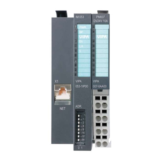
VIPA System SLIO Hardware description Structure > Interfaces 3.2 Structure 053-1IP00 Locking lever terminal module Labelling strip bus interface LED status indication bus interface Labelling strip power module LED status indication power module Backplane bus DC 24V power section supply Power module Twisted pair interface for EtherNet/IP 10 Unlocking lever power module... -
Page 34: Address Switch
Hardware description VIPA System SLIO Structure > Address switch PM - Power module For wires with a core cross-section of 0.08mm up to 1.5mm Pos. Function Type Description not connected DC 24V DC 24V for power section supply GND for power section supply Sys DC 24V DC 24V for electronic section supply not connected... -
Page 35: Leds
VIPA System SLIO Hardware description Structure > LEDs Changes of the IP address only take effect on PowerON or an automatic reset. Changes during operation are not rec- ognized! 3.2.3 LEDs Bus-Interface Description · Bus interface is power supplied green ·... -
Page 36: Technical Data
Hardware description VIPA System SLIO Technical Data LEDs power module Description green green ● ○ Power section supply OK ● ● ○ Electronic section supply OK ● Fuse electronic section supply defective on: ● | off: ○ | not relevant: X 3.3 Technical Data Order no. - Page 37 VIPA System SLIO Hardware description Technical Data Order no. 053-1IP00 Racks, max. Modules per rack, max. Number of digital modules, max. Number of analog modules, max. Communication Fieldbus EtherNet/IP Type of interface Ethernet 10/100 MBit Connector RJ45 Topology Star topology Electrically isolated ü...
-
Page 38: Deployment
Deployment VIPA System SLIO Basics EtherNet/IP Deployment 4.1 Basics EtherNet/IP General EtherNet/IP (Ethernet Industrial Protocol) is an open standard for industrial networks, which is real-time capable. EtherNet/IP is devel- oped by ODVA (Open DeviceNet Vendor Association) and is standar- dized in IEC 61158. Especially in the U.S. market EtherNet/IP is a standard in communication. -
Page 39: Basics - Ip Address And Subnet
VIPA System SLIO Deployment Basics - IP address and subnet Transfer medium EtherNet/IP uses as transfer medium Ethernet cable. EtherNet/IP can be operated in star topology via an already existing company network. To operate an EtherNet/IP network at least 1 scanner (master) is required. - Page 40 Deployment VIPA System SLIO Basics - IP address and subnet Subnet A TCP-based communication via point-to-point, hub or switch con- nection is only possible between stations with identical Network-ID and Subnet-ID! Different area must be connected with a router. The subnet mask allows you to sort the resources following your needs.
-
Page 41: Setting The Ip Address
VIPA System SLIO Deployment Setting the IP address Never choose an IP address with Host-ID=0 or Host- ID=maximum! (e.g. for class B with subnet mask = 255.255.0.0, the "172.16.0.0" is reserved and the "172.16.255.255" is occupied as local broadcast address for this network.) 4.3 Setting the IP address Setting possibilities... -
Page 42: Operating Modes
Deployment VIPA System SLIO Operating modes Description = 16 = 32 = 64 Changes of the IP address only take effect on PowerON or an automatic reset. Changes during operation are not rec- ognized! Setting the IP address The EtherNet/IP coupler supports the setting of the IP address by Ä... -
Page 43: Web Server
VIPA System SLIO Deployment Web server Transitions 1 Transition from Idle to Operational: As soon as a communication connection to at least one scanner exists respectively at least one scanner is in "Run mode". 2 Transition Operational to Idle: As soon there is no communication connection to a scanner respectively every scanner is in "Idle mode". - Page 44 Deployment VIPA System SLIO Web server [1] Module list: EtherNet/IP coupler and System SLIO modules in installed order [2] Functions for the module selected in the module list [3] Information respectively input area of the corresponding function For fast diagnostics, missing or wrong configured modules are represented red coloured in the module list after refreshing the web page.
- Page 45 VIPA System SLIO Deployment Web server Firmware With this function you can bring in a firmware update. You can get the appropriate firmware file from VIPA. During the firmware update, SF and MS (red) are blinking alternately. When the update is finished all the red LEDs are switched ON.
- Page 46 Deployment VIPA System SLIO Web server Web page with selected module Info Here product name, order number, serial number, firmware version and hardware state number of the according module are listed. Data At Data the states of the inputs respectively outputs are listed. In addition, you can directly control the outputs of the corresponding module.
-
Page 47: Accessing The System Slio
VIPA System SLIO Deployment Accessing the System SLIO > Overview 4.6 Accessing the System SLIO 4.6.1 Overview The EtherNet/IP coupler can control maximally 64 system SLIO modules. A system SLIO module can contain 1 ... 60byte I/O data. For the transport of this data stream, the data must be divided into EtherNet/IP packages and encapsulated. -
Page 48: Accessing I/O Area
Deployment VIPA System SLIO Accessing the System SLIO > Accessing I/O area Please consider the System SLIO power and clamp mod- ules do not have any module ID. These may not be recog- nized by the EtherNet/IP coupler and so are not listed and considered during slot allocation. -
Page 49: Accessing The Parameter Data
VIPA System SLIO Deployment Accessing the System SLIO > Accessing the parameter data Structure of the Input Structure Field name Data type Field value data (Instance ID 0x0A) Header Interrupt- USINT Interrupt and diagnostics Flags flags. An interrupt is pending when the corresponding bit is set. - Page 50 Deployment VIPA System SLIO Accessing the System SLIO > Accessing the parameter data Parameterization via the With the first start-up modules, which were parameterizable, operate web page with their default parameters. If you want to change parameters the EtherNet/IP coupler respectively the corresponding modules may be parameterized via the integrated Web page.
- Page 51 VIPA System SLIO Deployment Accessing the System SLIO > Accessing the parameter data Error codes Code Description 0x0000 Command has been executed without error. 0x0001 Configuration in FORWARD_OPEN could not be read. 0x0002 Unknown command in config assembly. 0x0003 Length in config assembly is not correct. 0x0004 Data missing for the command.
-
Page 52: Accessing Diagnostics Data
Deployment VIPA System SLIO Deployment of FORWARD_OPEN Code Description 0x001D Initialization: Config assembly could not be added. 0x001E Initialization: Identity object could not be initialized. 0x001F Initialization: Identity object could not be set. 0x0022 SetModTypeRange: There were more modules con- figured as exist. - Page 53 VIPA System SLIO Deployment Deployment of FORWARD_OPEN Example Here an example of FWD_OPEN: CMD 1: Ignore Webconfig: 01 00 CMD 2: Number of modules (5): 03 01 05 CMD 3: SetModuleType yy to Pos 3: 04 05 y4 y3 y2 y1 03 The specification for the type has to take place here in the little- endian format (least-significant byte first) CMD 4: End of Config: 00...
-
Page 54: Command Ids
Deployment VIPA System SLIO Deployment of FORWARD_OPEN > Command IDs 4.7.1 Command IDs Below there is a list of all the commands, which can be used in a FORWARD_OPEN config assembly. Please configure that the config assembly can be limited any time by means of the command EndOfCfg. - Page 55 VIPA System SLIO Deployment Deployment of FORWARD_OPEN > Command IDs EndOfCfg (0x00) The command EndOfCfg (0x00) specifies that the configuration fin- ishes at the inserted position. The subsequent commands after this command are ignored. Structure Field Data type Value Designation name Command USINT...
- Page 56 Deployment VIPA System SLIO Deployment of FORWARD_OPEN > Command IDs SetIOStart (0x07) The command SetIOStart (0x07) defines the I/O area of the System SLIO bus image, which is to be cyclically transferred in the selected assembly AsmId. This is only possible with static Assemblies (0x14 - 0x1D).
- Page 57 VIPA System SLIO Deployment Deployment of FORWARD_OPEN > Command IDs SetModType (0x04) The command SetModType (0x04) specifies the module ID ModID of the module at position Pos. Structure Field Data type Value Designation name Command USINT 0x04 SetModType header Length USINT 0x05 Length of the...
-
Page 58: Ethernet/Ip - Objects
Deployment VIPA System SLIO EtherNet/IP - Objects > Standardized EtherNet/IP Objects SetModParam (0x06) The command SetModParam (0x06) specifies the module parameter Para of the module at position Pos. A description of the parameters may be found in the manual of the according System SLIO module. To get the current parameters as basis record set for parameterization, you can use a ‘class3 connection’... -
Page 59: Vipa Specific Ethernet/Ip Objects
VIPA System SLIO Deployment EtherNet/IP - Objects > VIPA specific EtherNet/IP objects Object classes Description TCP/IP (0xF5) Configuration of the TCP/IP interface (e.g. IP address, Netmask, Gateway) Assembly (0xF4) Combines more attributes in one I/O con- nection Custom Objects Self-defined objects More information about the standardized EtherNet/IP object classes may be found in the according EtherNet/IP respectively CIP standard of the ODVA (Open DeviceNet... - Page 60 Deployment VIPA System SLIO EtherNet/IP - Objects > VIPA specific EtherNet/IP objects Diagnostics and inter- With this class the diagnostics and interrupt specific settings can be rupt class (code: 0x65) accessed. If this data have to be manually reset, this happens by the module class.
- Page 61 VIPA System SLIO Deployment EtherNet/IP - Objects > VIPA specific EtherNet/IP objects Structure of the interrupt and diagnostic data Field name Data type Field value USINT Module position (1 ... 64) Length UINT Length of the interrupt and diag- nostics data Data ARRAY of BYTE Interrupt and diagnostics data in...
- Page 62 Deployment VIPA System SLIO EtherNet/IP - Objects > VIPA specific EtherNet/IP objects Structure of the interrupt and diagnostics data Field name Data type Field value USINT Module position (1 ... 64) Length UINT Length of the interrupt and diagnostics data Data ARRAY of BYTE Interrupt and diagnostics data...
- Page 63 VIPA System SLIO Deployment EtherNet/IP - Objects > VIPA specific EtherNet/IP objects Coupler configuration Byte Content Byte 0 Bit 0: IgnoreWebConfig Bit 1: Auto Reset ProcessAlarmflag Bit 2: Auto Reset DianosticAlarmflag Bit 3: Always Send Transmit Addr Bit 4-7: reserved Byte 1 Number of plugged modules Byte 2 - n...
- Page 64 Deployment VIPA System SLIO EtherNet/IP - Objects > VIPA specific EtherNet/IP objects Since an I/O connection can only transfer a maximum of 496byte I/O data (less interrupt header and length), with SetIOStart a second con- nection can be opened over which the defined start area is trans- Ä...
- Page 65 VIPA System SLIO Deployment EtherNet/IP - Objects > VIPA specific EtherNet/IP objects Byte Type Content LWORD Hardware interrupt: Bit 0: Module 1 Bit 1: Module 2 Bit 63 ... 2: reserved LWORD Diagnostics interrupt: Bit 0: Module 1 Bit 1: Module 2 Bit 63 ...
- Page 66 Deployment VIPA System SLIO EtherNet/IP - Objects > VIPA specific EtherNet/IP objects 4.8.2.2 Example Configuration at a Rockwell scanner Here the following settings are necessary: HB300 | IM | 053-1IP00 | GB | 13-50...
Need help?
Do you have a question about the VIPA IM 053IP and is the answer not in the manual?
Questions and answers