
Related Manuals for Bender COMTRAXX MK800


Summary of Contents for Bender COMTRAXX MK800
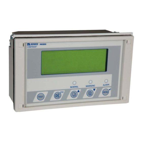
- Page 1 Manual COMTRAXX® MK800 Alarm indicator and test combination Software version: 4.1x MK800_D00053_00_M_XXEN/07.2015...
- Page 2 Bender GmbH & Co. KG © Bender GmbH & Co. KG P.O. Box 1161 • 35301 Gruenberg • Germany All rights reserved. Londorfer Straße 65 • 35305 Gruenberg • Germany Reprinting only with permission Tel.: +49 6401 807-0 • Fax: +49 6401 807-259 of the publisher.
-
Page 3: Table Of Contents
Table of Contents 1. How to get the most out of this manual ..........7 How to use this manual ..................7 Explanation of symbols and notes ..............8 2. Safety instructions .................. 9 Intended use ......................9 Qualified personnel ....................10 General safety instructions ................ - Page 4 Table of contents 4.1.3 Control panel mounting without enclosure ..........21 4.1.4 Control panel mounting with enclosure ............22 4.1.5 Use bezel frame ...................... 23 4.1.6 Surface-mounting enclosure ................24 Connection ......................26 4.2.1 Connection details ....................27 4.2.2 Wiring diagram ....................... 28 4.2.2.1 Connection assignment MK800-12 ............
- Page 5 Table of contents 7.2.3 Test function ......................55 8. Menu mode: Operation and setting ..........57 Switching on and calling the main menu ............. 57 Menu overview diagram ..................59 Main menu functions ................... 60 The main menu ...................... 60 8.4.1 Exit ..........................
- Page 6 Table of contents 9. Technical data ..................83 Technical data ......................83 9.1.1 Standards, approvals and certifications ............87 Ordering information ................... 87 MK800_D00053_00_M_XXEN/07.2015...
-
Page 7: How To Get The Most Out Of This Manual
Although great care has been taken in the drafting of this operating manual, it may nev- ertheless contain errors and mistakes. Bender cannot accept any liability for injury to persons or damage to property resulting from errors or mistakes in this manual. -
Page 8: Explanation Of Symbols And Notes
How to get the most out of this manual 1.2 Explanation of symbols and notes The following terms and symbols are used to denote hazards and instructions in Bender documentation: This signal word indicates that there is a high risk of danger that will result in death or serious injury if not avoided. -
Page 9: Safety Instructions
2. Safety instructions 2.1 Intended use The universal MK800 alarm indicator and test combination is used for visual and audible ® indication of operating status and alarm messages from Bender's EDS, RCMS, ATICS ® and MEDICS systems. ® In MEDICS... -
Page 10: Qualified Personnel
Compliance with test intervals. 2.2 Qualified personnel Only appropriately qualified personnel may work with the Bender devices. Personnel who are familiar with the installation, commissioning and operation of the equipment and have undergone appropriate training are considered qualified. Personnel must have read this manual and understood all safety-related instructions. -
Page 11: General Safety Instructions
Bender devices are designed and built in accordance with the state of the art and accept- ed rules in respect of technical safety. However, the use of such devices may introduce risks to life and limb of the user or third parties and/or result in damage to Bender equip- ment or other property. - Page 12 Safety instructions MK800_D00053_00_M_XXEN/07.2015...
-
Page 13: System Description
3. System description ® 3.1 MEDICS The MK800 alarm indicator and test combinations are integral components of the MED- ® ® system. MEDICS is an intelligent system that guarantees safe power supply in medical locations. ® Example of a section of a hospital where a MEDICS system is installed: MK800_D00053_00_M_XXEN/07.2015... -
Page 14: Characteristics
System description Legend to illustration above MK800 Alarm indicator and test combination RCMS… Residual current monitoring systems for TN-S systems SMI472 Signal converter for third-party systems (e.g. med. gases, BSV systems) TM… Alarm indicator and operator panel UFC107E… Changeover and monitoring module for IT systems with insulation fault location system EDS…... - Page 15 System description time there is an audible signal (can be acknowledged/muted). If a second message is re- ceived whilst the first is still pending, the audible signal will sound again and the mes- sages will appear alternately on the LC display. In addition, the address of the device triggering the alarm can be called up.
-
Page 16: Functionality
System description 3.3 Functionality 3.3.1 Display/operating elements The backlit display features 4 lines of 20 characters each. It assists medical and technical personnel during the decision-making process with information that is always clear and unambiguous. Every alarm message comprises three lines which appear spontaneously and three additional lines which can be displayed at the touch of a button. -
Page 17: History Memory
TMK-history PC software. 3.4 Versions 3.4.1 MK800-12 The MK800-12 is used for visual and audible indication of alarms from Bender EDS, ® RCMS and MEDICS systems and for testing assigned devices (insulation monitoring de- vices, LIM, GFCI). -
Page 18: Internal Bms Bus
System description 3.4.3.1 Internal BMS bus The internal BMS bus is used for communication with BMS bus devices, – e.g. modules like UMC…, UMA… , UFA…, UFC…, LFC…, ATICS – or devices like RCMS…, EDS…, SMI…, SMO…, alarm indicator and operator panels The MK800 is the master whenever the address is set to 1. -
Page 19: Installation And Connection
4. Installation and connection 4.1 Installation Overview of enclosure variants The MK800 is suitable for flush-mounting as well as for installation in a control panel or cavity wall. The MK800E is only suitable for panel mounting without rear cover. The MK800A and MK800AF in the surface-mounting enclosure are suitable for surface mounting. -
Page 20: Cavity Wall Mounting
Installation and connection Flush-mounting 1. Insert the cardboard that has been supplied into the flush-mounting enclo- sure to stabilise the enclosure and to provide protection against pollution during mounting. 2. Insert the enclosure so that it is flush with the wall surface. The flush-mount- ing enclosure must not be installed lopsidedly or warped, and must not be installed too deep below the surface. -
Page 21: Control Panel Mounting Without Enclosure
Installation and connection 4.1.3 Control panel mounting without enclosure For mounting in panels/doors the MK800 can also be delivered without enclosure: Version MK800E… (refer to "Ordering information" on page 87). Dimension diagram MK800E… COMTRAXX © Fig. 4.3: Dimensions in mm. Example: Door mounting Mounting in panel without enclosure 1. -
Page 22: Control Panel Mounting With Enclosure
Installation and connection 4.1.4 Control panel mounting with enclosure The MK800 can be protected by an enclosure also when it is inserted in a control panel: Dimension diagram MK800 with flush-mounting enclosure UP800 COMTRAXX © Fig. 4.4: . Dimensions in mm. Example: Door mounting with flush-mounting enclosure Control panel mounting with enclosure 1. -
Page 23: Use Bezel Frame
Installation and connection 4.1.5 Use bezel frame The MK800 can optionally be covered with a bezel frame. This frame is not included in the scope of delivery and has to be ordered separately (refer to "Ordering information" on page 87). COMTRAXX ©... -
Page 24: Surface-Mounting Enclosure
Installation and connection 4.1.6 Surface-mounting enclosure Dimension diagram surface-mounting enclosure MK800A-11/MK800A-12 MK800_D00053_00_M_XXEN/07.2015... - Page 25 Installation and connection Dimension diagram surface-mounting enclosure with door MK800AF-11/ MK800AF-12 Installation of the surface-mounting enclosure A smooth and even surface is a precondition for installation. Only the fas- tening screws specified below should be used. Failure to observe this can result in deformation or damage to the enclosure.
-
Page 26: Connection
Installation and connection 4.2 Connection Risk of electric shock! Before fitting the enclosure and working on the device connections, make sure that the power supply has been disconnected. Failure to comply with this requirement will expose personnel to the risk of DANGER an electric shock. -
Page 27: Connection Details
Installation and connection 4.2.1 Connection details Connect the MK800 to the supply voltage U (terminals +/-). – If you are connecting the MK800 to a DC 24 V supply: Take the line voltage drop into account if you are using long supply cables for the supply voltage. -
Page 28: Wiring Diagram
Installation and connection 4.2.2 Wiring diagram MK800_D00053_00_M_XXEN/07.2015... - Page 29 MK800 or TM800. SMI472-12 signal converters can also be connected. Internal BMS bus connection. Various Bender devices with a BMS bus inter- face can be connected to the BMS bus. These may include: Insulation moni- toring devices 107TD47, control devices PRC487, residual current monitors RCMS470 and many more.
-
Page 30: Connection Assignment Mk800-12
Installation and connection 4.2.2.1 Connection assignment MK800-12 The MK800-12 edition receives all messages from the BMS bus. These messages can be received, for example, from an 107TD47, an MK800-11, a signal converter SMI47x, an EDS… or a RCMS…. Supply voltage U looped through connection for supply voltage U Note: Make sure that the power supply of the MK800 is isolated from PE. -
Page 31: Examples For Bms Bus Connection And Addressing
Installation and connection 4.2.3 Examples for BMS bus connection and addressing Missing or incorrectly installed terminating resistors (e.g. in the middle of the bus) will cause bus instability. Please also note the information in the "BMS bus" operating manual. Example 1: Operating theatre and intensive care unit with two IT systems and three rooms UMA710 ATICS... - Page 32 Installation and connection Device Parameters Int. BMS bus address Ext. BMS bus address First changeover device UMA710 ATICS Bus address EDS151 Address Second changeover device UMC107E 107TD47 Bus address PRC487 Address Alarm indicator and test combinations Address MK2430-12 (Intensive care Test address unit 1) Alarm address...
- Page 33 Installation and connection Example 2: Intensive care area with two IT systems and four rooms UFA710 Intensiv A, B ATICS EDS151 EDS151 int. BMS int. BMS ext. BMS The alarm indicator and test combinations MK… in the intensive care units A and B or ®...
- Page 34 Installation and connection Device Parameters Int. BMS bus address Ext. BMS bus address Alarm indicator and test combinations Address MK2430-12 (Intensive care Test address unit A) Alarm address 1, 3, 4, 5 Individual alarms Address MK800-12 (Intensive care Test address unit B) Alarm address 2, 3, 4, 111...
-
Page 35: Address Settings And Their Meaning
Installation and connection 4.2.4 Address settings and their meaning Display Setting Setting Meaning on TM/ in TMK-SET External Internal MK800 address address 0 (ext bus on) 0 (ext bus on) TM/MK itself dig. IN* 0 (ext bus off ) M = own addr. TM/MK itself dig. - Page 36 Installation and connection Explanatory notes to digital inputs (only MK800-11) Alarm messages from digital inputs on TM/MK800 are always displayed on the device itself regardless of whether an individual message has been programmed or not (exception: the channel is deactivated). An entry into the alarm address table is not required.
-
Page 37: Commissioning And Testing
5. Commissioning and testing Start commissioning according to the following commissioning pattern: 1. Tests before switching on 2. Tests after switching on 3. Set parameters (parameterisation) – Settings at the MK800 – Settings in the TMK-SET software 4. Tests after parameter setting Write down all settings and keep it together with the device and installa- tion documentation. -
Page 38: Tests Before Switching On
Commissioning and testing 5.1 Tests before switching on Continue with chapter „5.2 Tests after switching on“ MK800_D00053_00_M_XXEN/07.2015... -
Page 39: Tests After Switching On
Commissioning and testing 5.2 Tests after switching on Continue with chapter „5.3 Make settings (parameterisation)“ 5.3 Make settings (parameterisation) All settings can be carried out via the TMK-SET software. Alternatively, some settings can be carried out via the MK800 menu (see diagrams). MK800_D00053_00_M_XXEN/07.2015... -
Page 40: Settings On The Mk800
Commissioning and testing 5.3.1 Settings on the MK800 For details refer to "Menu 4: Settings" on page 63. Continue with chapter „5.3.3 Tests after parameter setting“ MK800_D00053_00_M_XXEN/07.2015... -
Page 41: Settings Using The Tmk-Set Software
Commissioning and testing 5.3.2 Settings using the TMK-SET software Continue with chapter „5.3.3 Tests after parameter setting“ MK800_D00053_00_M_XXEN/07.2015... -
Page 42: Tests After Parameter Setting
Commissioning and testing 5.3.3 Tests after parameter setting (*) Messages which can be created by a BMS device are simulated. MK800_D00053_00_M_XXEN/07.2015... -
Page 43: Periodic Verification And Service
Commissioning and testing 5.4 Periodic verification and service 5.4.1 Periodic verification The following periodic verification must be performed on electrical installations in com- pliance with the local or national regulations that apply. For your Bender products, we recommend: Task Interval... -
Page 44: Service And Support
Repair, calibration, testing and analysing of Bender products Hardware and software update for Bender devices Delivery of replacement devices for faulty or incorrectly delivered Bender devices Extended warranty for Bender devices with in-house repair service or replace- ... -
Page 45: Maintenance
Commissioning and testing Field Service On-site service for all Bender products Commissioning, parameter setting, maintenance, troubleshooting for Bender products Analysis of the electrical installation in the building (power quality test, EMC test, thermography) Practical training courses for customers ... - Page 46 Commissioning and testing MK800_D00053_00_M_XXEN/07.2015...
-
Page 47: Troubleshooting
6. Troubleshooting 6.1 MK800 error messages The following errors are recognised by the MK800 module and indicated on the display. The buzzer emits a beep code corresponding to the error number every 10 seconds. MK800..-11 only: If the function "Device error" has been set in the "Settings menu 11: Re- lays", the alarm relay will also switch. - Page 48 None history memory is carried out because of voltage inter- ruption. Overflow ERROR (11) Stack Error Write down the error code and contact Bender Service. Checksum ERROR Program memory defective Replace MK800* Address external Address of the MK800 on the...
-
Page 49: Malfunctions
Troubleshooting Display Description Task I2C-1-Error Replace MK800* C-Bus-Interrupt * Please write down the error, the error number and if applicable the error code. This infor- mation facilitates the diagnosis and repair of the device. 6.2 Malfunctions List of possible errors and proposals for elimination of the faults. This error list does not claim to be exhaustive. - Page 50 Troubleshooting Errors Possible cause and actions Functional error of the digital inputs. Digital inputs not correctly set with TMK-SET. Defec- tive connection (does not match pre-assignment). Incorrect setting "neutral/medical". MK800_D00053_00_M_XXEN/07.2015...
-
Page 51: Operation
7. Operation This chapter can also be used by the medical personnel as a quick reference guide. 7.1 Operator control and display elements COMTRAXX © ********************************** SYSTEM READY ! LED and LCD LED "NORMAL": Power On indicator, green (only lights up if no warnings or alarms are pending) LED "WARNING": warning messages, yellow LED "ALARM": alarm messages, red... - Page 52 Operation Functions of the buttons: In operating mode In menu mode "TEST" button Press and release: LED test Press and hold down: Trigger the test No function of assigned devices (insulation moni- toring devices, LIM, GFCI). "ESC" button Exit function (without saving) button (mute button) or go up one menu level.
-
Page 53: Quick Reference Guide
Operation 7.2 Quick reference guide The illustrations below serve as examples. 7.2.1 Display under normal operating conditions There are no warnings or alarms pending. The green "Normal" LED is lit. The LC display shows the programmed standard display. ... - Page 54 Operation – Line 4: Status line = Consecutive number of message displayed = Number of pending messages = Message text page, in this case page 1 = Insulation fault location or test in progress (refer to table) 09:50 = Time (example) Possible displays during insulation fault location or testing: Meaning EDSa...
-
Page 55: Test Function
Operation – Line 4: Status line = Sequence number of the message displayed = Number of pending messages = Message text page, in this case page 2 = Insulation fault location or test currently in progress (see table) 09:50 = Time (example) When the messages are individually programmed, the message text dis- play may vary. - Page 56 Operation The following error codes are displayed in the event of an Isometer® failing the test: Error Error code description for the Error code description for the Note code 107TD47 ISOMETER® (hospital) IRDH… ISOMETER® (industry) No messages received from the No messages received from the ISOMETER®...
-
Page 57: Menu Mode: Operation And Setting
If there are no messages pending, the standard display will be shown when the starting procedure is completed. ******************** *** SYSTEM READY! ** Bender GmbH Grünberg 09:50 The TMK-SET software allows you to change the standard display and the message texts. - Page 58 Menu mode: Operation and setting Press the button "Menu" to open the main menu. 1.Exit 2.Values 3.History 4.Settings 5.Control 6.External devices 7.Info The following buttons can be used in the main menu: Exit function or go up one menu level ▲, ▼...
-
Page 59: Menu Overview Diagram
Menu mode: Operation and setting 8.2 Menu overview diagram The following diagram will help you to navigate through the menus: MK800_D00053_00_M_XXEN/07.2015... -
Page 60: Main Menu Functions
Menu mode: Operation and setting 8.3 Main menu functions Menu item Function Page 1. Exit Exit menu mode 2. Measured val- No function Displays history with information about messages, 3. History acknowledgements and associated times. 4. Settings Various settings for this MK800 This menu offers various options for controlling the 5. -
Page 61: Menu 3: History
Menu mode: Operation and setting 8.4.3 Menu 3: History The MK800 can store up to 1000 messages in the history memory (ring buffer). If more than 1000 messages are recorded by the MK800, message 1001 will overwrite the entry The "History" menu provides information about messages, acknowledgements and their time stamps. - Page 62 Menu mode: Operation and setting Possible displays in the last line of the history memory message text display: Text Meaning Address of the device triggering the message Address: (ee = external BMS bus address, iii = internal BMS bus address, kk= chan- ee/iii/kk nel no.
-
Page 63: Menu 4: Settings
11. Relay relay (alarm relay) on the MK800-11 12. Password Change password, activate/deactivate password. These settings can only be made by authorised Bender Service personnel. Retrieve information about the device 13. Service menu status, enter settings for special operating conditions and execute a firmware update. -
Page 64: Exit
Menu mode: Operation and setting 8.4.4.1 Exit Exit menu mode. 1.Exit 2.Alarm addresses 3.Test addresses 4.Value addresses 8.4.4.2 Settings menu 2: Alarm addresses Setting of the bus addresses of the devices the alarm messages of which are to be dis- played at this MK800. -
Page 65: Settings Menu 3: Test Addresses
Menu mode: Operation and setting Possible settings for the system number "Syst": Syst Meaning No text appears in line 1 of the alarm message. 01…04 Texts of "System 01" to "System 04" are displayed. Programmed text is displayed. Deletes the current line of the table 8.4.4.3 Settings menu 3: Test addresses Set the bus addresses for insulation monitoring devices (z. -
Page 66: Settings Menu 4: Value Addresses
Menu mode: Operation and setting Use the arrow buttons to select insulation monitoring de- vice "Type" and confirm with the "↵" button. MK800 always adds a new line at the end of the table which can be changed (e.g. 4 000 000 off). This way, other test ad- dresses can be activated. -
Page 67: Settings Menu 5: Digital Inputs
Menu mode: Operation and setting 8.4.4.5 Settings menu 5: Digital inputs Setting the operating behaviour for the digital inputs IN1…IN16 (for MK800-11 only). The following setting can be made individually for each input: "24V" (high) or "0V" (low). When the input is set to "24V" an alarm message will be sent when the voltage at the input is 10…30 V. - Page 68 Menu mode: Operation and setting Specific alarm messages These messages contain details regarding medical gases and BSV systems. Alarm messages for medical gases are signalled by the red "ALARM" LED and the buzzer sound. The buzzer can be set to mute (acknowledged). The buzzer sounds again every 15 minutes.
-
Page 69: Settings Menu 6: Buzzer (And Led)
Menu mode: Operation and setting 8.4.4.6 Settings menu 6: Buzzer (and LED) The buzzer will sound in the event of an alarm. Setting of the audio frequency and rep- etition rate of the two consecutive buzzer sounds. 1.Exit 2.Warning: 3.Alarm: 1. -
Page 70: Settings Menu 8: Clock
Menu mode: Operation and setting 8.4.4.8 Settings menu 8: Clock This menu is used to set the time, date and date format display. These settings remain stored after a supply failure for approx. 5 days. The clock adjusts itself automatically to the Central European Summertime (CEST) and Wintertime (CET). -
Page 71: Settings Menu 9: Language
Menu mode: Operation and setting 8.4.4.9 Settings menu 9: Language Selection of the language for menu operation and message display (alarm and operat- ing messages) at the MK800. Changes will be effective immediately. 1.Exit 2.Menu: English 3.Messg.: English 1. Exit Back to the main menu. -
Page 72: Settings Menu 10: Interface
Menu mode: Operation and setting 8.4.4.10 Settings menu 10: Interface Setting of the own device address and the transfer rate (baud rate) for the connection to the BMS bus. 1.Exit 2.Addr. ext.: 3.Baud ext.: 57600 4.Addr. int.: 1.Exit Back to the main menu. 2. -
Page 73: Settings Menu 11: Relays
Menu mode: Operation and setting 8.4.4.11 Settings menu 11: Relays Set the operation mode and function for the optional alarm relay of the alarm indicator and test combination. This menu only exists on the MK800..-11. 1.Exit 2.Operat.princ.: 3.Mode: Device error 1. -
Page 74: Settings Menu 12: Password
(except the Service menu) until menu mode is exited. 8.4.4.13 Settings menu 13: Service menu Only Bender service personnel are authorised to make settings in the Service menu. In the Service menu, information about the device status can be called up and settings for specific operating conditions can be made. -
Page 75: Menu 5: Control
Menu mode: Operation and setting 8.4.5 Menu 5: Control This menu offers various options for controlling individual devices or the overall system: Menu item Function Page 1. Exit Exit "Control" menu; go up one menu level 2. Reset Resetting all fault messages pending on the BMS bus (AlarmClear) Manual starting/stopping of test procedure on the EDS 3. -
Page 76: Control Menu 3: Eds Start/Stop
Menu mode: Operation and setting 8.4.5.3 Control menu 3: EDS Start/Stop Press the "↵" button to manually start and stop the measuring procedure of the EDS sys- tem. This function can only be activated by the master. The current status appears in the last line. -
Page 77: Control Menu 5: Reset Mode
External bus Devices connected to the external bus of this MK800 can be displayed and adjusted. If other Bender devices utilising an internal bus (TM…, MK…) are addressed via the exter- nal bus, also the devices connected to this internal bus can be displayed and adjusted. - Page 78 Menu mode: Operation and setting All devices connected to the BMS bus are indicated. Select the address of the external device to be displayed (e.g. EDS4xx-12 or RCMS4xx-12). 1. Exit (internal!) 001: MK800-11 V4.04 002: EDS470 V3.20 003: 107TD47 V2.52 Address, type and version of the connected device are displayed.
-
Page 79: Menu 7: Info
MK800-11 Addr.:01/001 Software 4.02 D279 Date: 02/09/12 www.bender.de Information regarding device type, firmware version and last time assignments were transmitted. Assignments are settings carried out via PC software (e.g. TMK-SET): Enter standard text Assign texts and functions to the alarm messages and digital inputs of the MK800 ... -
Page 80: Overview Of Setting Options
Menu mode: Operation and setting ▼(press twice) The alarm addresses, test addresses and individual mes- sages and the number of the devices will be displayed. Switching commands: On MK800 without function. Alarm addresses: Test addresses: Indiv. Assignm.: Switch.cmd.: 00/00 ↵ Go back to the main menu 8.5 Overview of setting options The MK800 supports various settings. - Page 81 Menu mode: Operation and setting MK800_D00053_00_M_XXEN/07.2015...
- Page 82 Menu mode: Operation and setting MK800_D00053_00_M_XXEN/07.2015...
-
Page 83: Technical Data
9. Technical data 9.1 Technical data Insulation coordination according to IEC 60664-1 Rated insulation voltage ......................AC 250 V Rated impulse withstand voltage/pollution degree ..............4 kV/3 Supply voltage Supply voltage ........................AC/DC 24 V Frequency range ..................... AC 40…60 Hz/DC Operating range .................. - Page 84 Technical data Inputs (MK800…-11 only) Digital inputs ........................16 (IN1…IN16) Galvanic separation ..........................yes Control of digital inputs ..........via potential-free contacts/extraneous voltage Operation mode ............N/O, N/C operation, off, selectable for each input Factory setting ............................Off Voltage range (high) ....................AC/DC 10…30 V Voltage range (low) ......................
- Page 85 Technical data Colours Front foil ................ RAL 7035 (light grey) / RAL 7040 (basalt grey) Marking ........................ RAL 5005 (signal blue) Front plate ....................... RAL 7035 (light grey) Switching elements (MK800-11 only) Number ........................1 changeover contact Function ..........................programmable Operation mode .................
- Page 86 Technical data Connection Connection ...................... pluggable screw terminals Connection properties (supply voltage, BMS bus): Rigid/flexible/conductor sizes ..........0.2…2.5/0.2…2.5 mm /AWG 24-12 Flexible with ferrules, without/with plastic sleeve ........0.25…2.5/0.25…2.5 mm Connection properties (inputs): Rigid/flexible/conductor sizes ..........0.08…1.5/0.08…1.5 mm / AWG 28-16 Flexible with ferrules, without/with plastic sleeve ........
-
Page 87: Standards, Approvals And Certifications
Technical data 9.1.1 Standards, approvals and certifications The MK800 alarm indicator and test combination meets the requirements of the stand- ards DIN VDE 0100-710 (VDE 0100-710) and IEC 60364-7-710. 9.2 Ordering information Type Description Art. No. MK800-11 Alarm indicator and test combination acc. to B 9510 0100 DIN VDE 0100-710, with BMS bus and USB interface, 16 digital inputs, one... - Page 88 Technical data Type Description Art. No. UP800 Flush-mounting enclosure for MK800 B 9510 0110 BR800-1 Bezel frame silver for MK800 B 9510 0111 BR800-2 Bezel frame white for MK800 B 9510 0112 Parameteri- - TMK-SET V 4.x parameterisation software for by Internet sation MK2430, MK800, TM800,...
- Page 89 Display 16 Display and operating units 14 Display functions 9 Baud rate 72 Displaying information 77 Beep code 47 Disturbances 11 Bender service personnel 74 BMS bus - internal 18 BMS bus address 72 electrostatic electricity 26 Buzzer ENTER button 52...
- Page 90 INDEX Firmware version 57 MEDICS® 13 Flush-mounting enclosure 20 Menu mode 58 Front panel 21 Message text display 62 Functional test 43 Message texts 15 Functionality 14 MK800-11 17 MK800-12 17 Monitoring modules 14 Gases - medical 9 Gateways 14 National languages 15 Navigation 59 Normal...
- Page 91 INDEX - Error code 55 - Error code note 56 Relay mode 73 Test addresses 65 Relay output 27 Test communication 76 Relay outputs 14 Test intervals 10 Replacement parts 11 Test procedure 76 Reset 75 Tests 37 Reset mode 77 Text display 16 Risks 11 Text messages 17...
- Page 92 MK800_D00053_00_M_XXEN/07.2015...
- Page 96 Bender GmbH & Co. KG P.O. Box 1161 • 35301 Gruenberg • Germany Londorfer Straße 65 • 35305 Gruenberg • Germany Tel.: +49 6401 807-0 • Fax: +49 6401 807-259 E-mail: info@bender.de • www.bender.de Photos: Bender archives.
Need help?
Do you have a question about the COMTRAXX MK800 and is the answer not in the manual?
Questions and answers