Chapters
Table of Contents

Related Manuals for Homematic IP HmIP-DRDI3


Summary of Contents for Homematic IP HmIP-DRDI3
- Page 1 Installations- und Bedienungsanleitung Installation and operating manual Dimmaktor für Hutschienen- S. 2 montage – 3-fach Dimming Actuator for DIN rail p. 39 mount – 3 channels HmIP-DRDI3...
- Page 2 Lieferumfang Anzahl Bezeichnung Homematic IP Dimmaktor für Hutschienenmontage – 3-fach Bedienungsanleitung Dokumentation © 2019 eQ-3 AG, Deutschland Alle Rechte vorbehalten. Ohne schriftliche Zustimmung des Herausgebers darf diese Anleitung auch nicht auszugsweise in irgendeiner Form reproduziert werden oder unter Verwendung elektronischer, mechanischer oder chemischer Verfahren verviel- fältigt oder verarbeitet werden.
- Page 6 Anschluss von verschiedenen Lasten (Ausgänge) und Versorgungsspannung Connection of different loads (outputs) and supply voltage...
- Page 7 Anschluss von Tastern/Schaltern (Eingänge) Connection of push-buttons/switches (inputs)
- Page 8 Homematic IP...
-
Page 12: Table Of Contents
Inhaltsverzeichnis Hinweise zur Anleitung ..........13 Gefahrenhinweise ............13 Funktion und Geräteübersicht ........19 Allgemeine Systeminformationen ......21 Inbetriebnahme ..............22 Installationshinweise ............22 Montage und Installation ..........24 Anlernen ................27 Bedienung ................29 Fehlerbehebung ............. 31 Fehlercodes und Blinkfolgen ..........31 Befehl nicht bestätigt ............32 Duty Cycle ................ -
Page 13: Hinweise Zur Anleitung
Hinweise zur Anleitung Hinweise zur Anleitung Lesen Sie diese Anleitung sorgfältig, bevor Sie Ihr Home- matic IP Gerät in Betrieb nehmen. Bewahren Sie die An- leitung zum späteren Nachschlagen auf! Wenn Sie das Gerät anderen Personen zur Nutzung über- lassen, übergeben Sie auch diese Anleitung. Benutzte Symbole: Achtung! Hier wird auf eine Gefahr hingewiesen. - Page 14 Gefahrenhinweise Verwenden Sie das Gerät nicht, wenn es von au- ßen erkennbare Schäden, z. B. am Gehäuse, an Bedienelementen oder an den Anschlussbuchsen ausweist. Lassen Sie das Gerät im Zweifelsfall von einer Fachkraft prüfen. Betreiben Sie das Gerät nur in trockener sowie staubfreier Umgebung, setzen Sie es keinem Ein- fluss von Feuchtigkeit, Vibrationen, ständiger Sonnen- oder anderer Wärmeeinstrahlung, über-...
- Page 15 Gefahrenhinweise Der Aktor ist Teil der Gebäudeinstallation. Bei der Planung und Errichtung sind die einschlägigen Normen und Richtlinien des Landes zu beachten. Der Betrieb des Geräts ist ausschließlich am 230 V/50 Hz-Wechselspannungsnetz zulässig. Arbeiten am 230-V-Netz dürfen nur von einer Elektrofachkraft (nach VDE 0100) erfolgen.
- Page 16 Gefahrenhinweise Beachten Sie vor Anschluss eines Verbrauchers die technischen Daten, insbesondere die maximal zulässige Schaltleistung der Lastkreise und Art des anzuschließenden Verbrauchers. Belasten Sie den Aktor nur bis zur angegebenen Leistungsgrenze. Für den sicheren Betrieb muss das Gerät in einen Stromkreisverteiler entsprechend VDE 0603, DIN 43871 (Niederspannungsunterverteilung (NSUV)), DIN 18015-x eingebaut werden.
- Page 17 Gefahrenhinweise Gefahr durch elektrischen Schlag. Vor Arbeiten am Gerät oder vor Auswechseln von Leuchtmit- teln Netzspannung freischalten und Sicherungs- automaten abschalten. Der Dimmaktor ist ausschließlich für Glühlampen sowie für Hochvolt-Halogenlampen und Nieder- volt- Halogenlampen mit elektronischen Transfor- matorensowie dimmbare LED-Lampen geeignet! Keine LED- oder Kompaktleuchtstofflampen an- schließen, die nicht ausdrücklich zum Dimmen geeignet sind.
- Page 18 Gefahrenhinweise Geräte mit elektronischen Netzteilen (z. B. Hoch- volt-LED-Leuchtmittel) stellen keine ohmschen Lasten dar. Sie können Einschaltströme von über 100 A erzeugen. Schalten solcher Verbraucher führt zu vorzeitigem Verschleiß des Aktors. Wir empfeh- len in solchen Fällen die Verwendung von Ein- schaltstrombegrenzern an den Schaltausgängen.
-
Page 19: Funktion Und Geräteübersicht
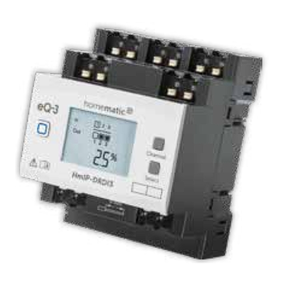
Funktion und Geräteübersicht Funktion und Geräteübersicht Der Homematic IP Dimmaktor – 3-fach lässt sich ein- fach auf einer Hutschiene in einem Stromkreisverteiler montieren. Einmal installiert, schaltet und dimmt er an- geschlossene Leuchten über drei potentialfreie, unab- hängige Kanäle. Im Homematic IP System kann der Dimmaktor die an- geschlossenen Leuchten komfortabel über angelernte... - Page 20 Funktion und Geräteübersicht Geräteübersicht (s. Abbildung 1): Systemtaste (Anlerntaste und LED) Channel-Taste Select-Taste LC-Display Anschlussklemmen für Taster/Schalter Kanal 1-3 Anschluss klemmen für Außenleiter (Kanal 1 und 2) Verrastung für die Hutschienenmontage Anschlussklemme Außenleiter (Geräteversor- gung/Kanal 3) Anschlussklemme Neutralleiter Anschlussklemmen für den Verbraucher (Last) Displayübersicht (s.
-
Page 21: Allgemeine Systeminformationen
Temperaturangabe (eingeschaltet, wenn Temperatur angezeigt wird) Allgemeine Systeminformationen Dieses Gerät ist Teil des Homematic IP Smart-Home- Systems und kommuniziert über das Homematic IP Funkprotokoll. Alle Geräte des Systems können komfor- tabel und individuell per Smartphone über die Home- matic ... -
Page 22: Inbetriebnahme
Inbetriebnahme Inbetriebnahme Installationshinweise Bitte notieren Sie sich vor der Installation die auf dem Gerät angebrachte Gerätenummer (SGTIN) und den Verwendungszweck, damit Sie das Gerät im Nachhinein leichter zuordnen können. Alter- nativ steht die Gerätenummer auch auf dem bei- liegenden QR-Code-Aufkleber. Hinweis! Installation nur durch Personen mit einschlägigen elektrotechnischen Kenntnissen und Erfahrungen!*... - Page 23 Inbetriebnahme oder abschranken; • Auswahl des geeigneten Werkzeuges, der Messgeräte und ggf. der persönlichen Schutzausrüstung; • Auswertung der Messergebnisse; • Auswahl des Elektroinstallationsmaterials zur Sicherstel- lung der Abschaltbedingungen; • IP-Schutzarten; • Einbau des Elektroinstallationsmaterials; • Art des Versorgungsnetzes (TN-System, IT-System, TT-System) und die daraus folgenden Anschlussbedin- gungen (klassische Nullung, Schutzerdung, erforderliche Zusatzmaßnahmen etc.).
-
Page 24: Montage Und Installation
Inbetriebnahme Montage und Installation Bitte lesen Sie diesen Abschnitt erst vollständig, bevor Sie mit der Installation beginnen. Die Laststromkreise müssen mit einem Leitungs- schutzschalter gemäß EN60898-1 (Auslösecha- rakteristik B oder C, max. 16 A Nennstrom, min. 6 kA Abschaltvermögen, Energiebegrenzungs- klasse 3) abgesichert sein. - Page 25 Inbetriebnahme und H), die gedimmte Phase (zum Verbraucher) an die Klemmen (J) sowie den Neutralleiter an die entsprechenden Klemmen (I) an (s. Abbildung 6+7). Es können beliebige Außenleiter (L1, L2, L3) angeschlossen werden. Die Eigenversorgung des Dimmaktors sowie die Versorgung des dritten Kanals erfolgt über die Klemmen L/3L und N/3N.
- Page 26 Inbetriebnahme Das Weiterverbinden (Durchschleifen) von Lei- tern über die Netzklemmen des Geräts zu ande- ren Geräten ist nicht erlaubt! • Schließen Sie externe Taster/Schalter an die An- schlussklemme IN1 bis IN3 (E) an (s. Abbildung 7). • Setzen Sie die Abdeckung des Stromkreisvertei- lers wieder auf.
-
Page 27: Anlernen
Bitte lesen Sie diesen Abschnitt erst vollständig, bevor Sie mit dem Anlernen beginnen. Richten Sie zunächst Ihren Homematic IP Access Point über die Homematic IP App ein, um weitere Homematic IP Geräte im System nutzen zu kön- nen. Ausführliche Informationen dazu finden Sie in der Bedienungsanleitung des Access Points. - Page 28 Inbetriebnahme Sie können den Anlernmodus manuell für weitere 3 Minuten starten, indem Sie die Systemtaste (A) kurz drücken (s. Abbildung 9). • Das Gerät erscheint automatisch in der Home- matic IP App. • Zur Bestätigung geben Sie in der App die letzten vier Ziffern der Gerätenummer (SGTIN) ein oder scannen Sie den QR-Code.
-
Page 29: Bedienung
Bedienung Bedienung Über die folgenden Tasten stehen Ihnen einfache Bedien- funktionen direkt am Gerät zur Verfügung: Systemtaste (A) • • Channel-Taste (B) Select-Taste (C) • externe Taster/Schalter (E) • Systemtaste Durch kurzes Drücken der Systemtaste (s. Abbildung 10) können Sie die LCD-Hintergrundbeleuchtung aktivieren. Channel-Taste Durch kurzes Drücken der Channel-Taste (s. - Page 30 Bedienung simuliert. Die verknüpften Aktoren können so geschaltet werden. Diese Funktion steht nicht zur Verfügung, wenn der Eingang für Schaltkontakte konfiguriert ist. Wenn Sie zuvor keinen Kanal ausgewählt haben, können Sie durch kurzes Drücken der Select-Taste die folgenden Anzeigen im LC-Display auswählen: •...
-
Page 31: Fehlerbehebung
Fehlerbehebung Fehlerbehebung Fehlercodes und Blinkfolgen Blinkcode/ Bedeutung Lösung LCD-Anzeige Kurzes oranges Anlernmodus Geben Sie die Blinken (alle aktiv letzten vier Ziffern 10 s) der Geräte- Seriennummer zur Bestätigung ein (s. „5.3 Anlernen“ auf Seite 27). 6x langes rotes Gerät defekt Achten Sie auf die Blinken Anzeige in Ihrer... -
Page 32: Befehl Nicht Bestätigt
Fehlerbehebung E12* Kanal über- Beachten Sie die lastet maximale Schaltleis- tung und reduzie- ren Sie die an den betroffenen Kanal angeschlossene Last entsprechend. E13* Kommuni- Kontrollieren Sie die kation mit Spannungsversor- Dimmerkanal gung des betroffe- gestört nen Kanals. E17* Firmware- Starten Sie den Update für Dimmaktor neu, um... -
Page 33: Duty Cycle
Erreichen des 1 %-Limits nicht mehr senden, bis diese zeitliche Begrenzung vorüber ist. Gemäß dieser Richtlinie, werden Homematic IP Geräte zu 100 % nor- menkonform entwickelt und produziert. Im normalen Betrieb wird der Duty Cycle in der Regel nicht erreicht. -
Page 34: Wiederherstellung Der Werkseinstellungen
Wiederherstellung der Werkseinstellungen Wiederherstellung der Werkseinstellungen Die Werkseinstellungen des Geräts können wie- derhergestellt werden. Dabei gehen alle Einstel- lungen verloren. Um die Werkseinstellungen des Geräts wiederherzustel- len, gehen Sie wie folgt vor: Drücken Sie für 4 s auf die Systemtaste (A), bis •... -
Page 35: Allgemeine Hinweise Zum Funkbetrieb
Gegebenheiten vor Ort eine wich- tige Rolle. Hiermit erklärt die eQ-3 AG, Maiburger Str. 29, 26789 Leer, Deutschland, dass der Funkanlagentyp Home- matic IP HmIP-DRDI3 der Richtlinie 2014/53/EU ent- spricht. Der vollständige Text der EU-Konformitätserklä- rung ist unter der folgenden Internetadresse verfügbar: www.homematic-ip.com... -
Page 36: Technische Daten
Technische Daten Technische Daten Geräte-Kurzbezeichnung: HmIP-DRDI3 Versorgungsspannung: 230 V~/50 Hz Stromaufnahme: 0,9 A max. (Ausgang Ka- nal 3: 200 VA) Leistungsaufnahme Ruhebetrieb: 0,5 W typ. (Displaybe- leuchtung aus, Ausgang Kanal 3 aus) Kanal 1 bis 2 Versorgungsspannung: 230 V~/50 Hz Stromaufnahme:... - Page 37 Technische Daten EN 60715 Schutzart: IP20 Umgebungstemperatur: -5 bis +40 °C Abmessungen (B x H x T): 72 x 90 x 69 mm (4 TE) Gewicht: 200 g Funk-Frequenzband: 868,0-868,60 MHz 869,4-869,65 MHz Max. Funk-Sendeleistung: 10 dBm Empfängerkategorie: SRD category 2 Typ.
- Page 38 Technische Daten Entsorgungshinweis Gerät nicht im Hausmüll entsorgen! Elektroni- sche Geräte sind entsprechend der Richtlinie über Elektro- und Elektronik-Altgeräte über die örtlichen Sammelstellen für Elektronik-Altgeräte zu entsorgen. Konformitätshinweis Das CE-Zeichen ist ein Freiverkehrszeichen, das sich ausschließlich an die Behörden wendet und keine Zusicherung von Eigenschaften beinhaltet.
- Page 39 Package contents Quantity Description Homematic IP Dimming Actuator for DIN rail mount – 3 channels User manual Documentation © 2019 eQ-3 AG, Germany All rights reserved. Translation from the original version in Ger- man. This manual may not be reproduced in any format, either in...
- Page 40 Table of Contents Information about this manual........41 Hazard information ............41 Function and device overview ........47 General system information ........49 Start-up ................49 Installation instructions ............. 49 Mounting and installation ..........51 Teaching-in ................54 Operation .................56 Troubleshooting .............58 Error codes and flashing sequences ......58 Command not confirmed ..........
-
Page 41: Information About This Manual
Information about this manual Please read this manual carefully before beginning operation with your Homematic IP component. Keep the manual so you can refer to it at a later date if you need to. If you hand over the device to other persons for use, hand over this manual as well. - Page 42 Hazard information Do not use the device if there are signs of damage to the housing, control elements or connecting sockets, for example. If you have any doubts, have the device checked by an expert. The device may only be operated in dry and dust- free environment and must be protected from the effects of moisture, vibrations, solar or other methods of heat radiation, excessive cold and...
- Page 43 Hazard information Only qualified electricians (to VDE 0100) are permitted to carry out work on the 230 V mains. Applicable accident prevention regulations must be complied with whilst such work is being carried out. To avoid electric shocks from the device, please disconnect the mains voltage (trip the miniature circuit-breaker).
- Page 44 Hazard information For secure operation, the device has to be installed in a power distribution panel according to VDE 0603, DIN 43871 (low-voltage sub- distribution board), DIN 18015-x. The installation must be carried out on a mounting rail (DIN rail) according to EN 60715.
- Page 45 Hazard information The dimming actuator is only suitable for light bulbs and high-voltage and low-voltage halogen lamps with electronic transformers as well as dimmable LED lamps! Do not connect LED or compact fluorescent lamps which are not expressly suitable for dimming.
- Page 46 Hazard information Devices with electronic power supply units (e.g. high voltage LED light sources) are no ohmic loads. They can generate inrush currents with more than 100 A. Switching such kind of loads may lead to premature wear of the actuator. In such cases, we recommend to use switch-on current limiters at the switching outputs.
-
Page 47: Function And Device Overview
Function and device overview Function and device overview The Homematic IP Dimming Actuator – 3 channels can be easily installed on a DIN rail within a distribution board. Once installed, it switches and dims connected luminaries via three potential-free, independent channels. - Page 48 Function and device overview Device overview (see figure 1): (A) System button (teach-in button and LED) (B) Channel button (C) Select button (D) LC display (E) Connecting terminal for push-button/switch channel 1-3 (F) Connecting terminals for phase conductor (channel 1 and 2) (G) DIN rail lock (H) Connecting terminals for phase conductor (power supply/channel 3)
-
Page 49: General System Information
General system information General system information This device is part of the Homematic IP smart home system and works with the Homematic IP radio protocol. All devices of the system can be configured comfortably and individually with the Homematic IP smartphone app. - Page 50 Start-up Incorrect installation can put • your own life at risk; • and the lives of other users of the electrical system. Incorrect installation also means that you are running the risk of serious damage to property, e.g. because of a fire. You may be personally liable in the event of injuries or damage to property.
-
Page 51: Mounting And Installation
Start-up Please note the insulation stripping length of the conductor to be connected, indicated on the device. Permitted cable cross sections for connecting to the switch actuator are: rigid cable [mm flexible cable without ferrule [mm 0.75.-2.5 0.75.-2.5 Mounting and installation Please read this entire section before starting to install the device. - Page 52 Start-up • Place the dimming actuator onto the DIN rail (see fig. 3). Make sure that you can read the letters on the device and display and that the connecting terminals of channel 1 and 3 are at the top. •...
- Page 53 Start-up The phase conductor connection is marked with an arrow pointing to the centre of the device, the switched phase conductor with an arrow pointing towards outside. To connect or loosen the conductor, the white actuation lever at the top of the clamp has to be pressed (see figure 5).
-
Page 54: Teaching-In
Teaching-in Read this entire section before starting the teach-in procedure. First set up your Homematic IP Access Point via the Homematic IP app to enable operation of other Homematic IP devices within your system. For further information, refer to the operating manual of the Access Point. - Page 55 Start-up To integrate the device into your system and to enable control via the free Homematic IP app, you must teach-in the device to your Homematic IP Access Point first. To teach-in the device, please proceed as follows: • Open the Homematic IP app on your smartphone.
-
Page 56: Operation
Operation Operation Via the following push-buttons, simple operating functions are available directly on the device: system button (A) • • channel button (B) select button (C) • external push-buttons/switches (E) • System button By pressing the system button briefly (see figure 10), you can activate the LCD background light. - Page 57 Operation This function is not available if the input has been configured for switch contacts. If you have not selected a channel previously, you can select the following options in the LC display by pressing the Select button briefly: • Duty cycle of the dimming actuator (in %) •...
-
Page 58: Troubleshooting
Troubleshooting Troubleshooting Error codes and flashing sequences Flashing code / Meaning Solution LC display Short orange Teach-in Enter the last four flashing (every mode active numbers of the 10 s) device serial number to confirm (see “5.3 Teaching-in” on page 54). 6x long red Device Have a look at... -
Page 59: Command Not Confirmed
Troubleshooting E12* Channel Observe the overloaded maximum switching capacity and reduce the load connected to the channel accordingly. E13* Communi- Check the power cation failure supply of the with dimming corresponding channel channel. E17* Firmware Restart the dimming update for actuator to begin dimming with the transfer of... -
Page 60: Duty Cycle
Devices must cease transmission when they reach the 1% limit until this time restriction comes to an end. Homematic IP devices are designed and produced with 100% conformity to this regulation. During normal operation, the duty cycle is not usually reached. -
Page 61: Restore Factory Settings
Restore factory settings Restore factory settings The factory settings of the device can be restored. If you do this, you will lose all your settings. To restore the factory settings of the device, proceed as follows: Press and hold down the system button (A) for 4 •... -
Page 62: General Information About Radio Operation
Hereby, eQ-3 AG, Maiburger Str. 29, 26789 Leer/Germany declares that the radio equipment type Homematic IP HmIP-DRDI3 is in compliance with Directive 2014/53/ EU. The full text of the EU declaration of conformity available following... -
Page 63: Technical Specifications
Technical specifications Technical specifications Device short name: HmIP-DRDI3 Supply voltage: 230 V~/50 Hz Current consumption: 0.9 A max. (output channel 3: 200 VA) Standby power consumption: 0.5 W typically (display lights off, output channel 3 off) Channel 1 to 2... - Page 64 Technical specifications (4 WM width) Weight: 200 g Radio frequency band: 868.0-868.60 MHz 869.4-869.65 MHz Maximum radiated power: 10 dBm Receiver category: SRD category 2 Typ. open area RF range: 190 m Duty cycle: < 1 % per h/< 10 % per h Subject to technical changes.
- Page 65 Technical specifications Information about conformity The CE sign is a free trading sign addressed exclusively to the authorities and does not include any warranty of any properties. For technical support, contact your specialist dealer.
- Page 66 Kostenloser Download der Homematic IP App! Free download of the Homematic IP app! Bevollmächtigter des Herstellers: Manufacturer’s authorised representative: eQ-3 AG Maiburger Straße 29 26789 Leer / GERMANY www.eQ-3.de...
Need help?
Do you have a question about the HmIP-DRDI3 and is the answer not in the manual?
Questions and answers