Chapters
Table of Contents

Related Manuals for Homematic IP HmIP-DRBLI4


Summary of Contents for Homematic IP HmIP-DRBLI4
- Page 1 Installations- und Bedienungsanleitung Installation and operating manual Jalousieaktor für Hutschienen- S. 2 montage – 4-fach Blind Actuator for DIN rail mount P. 36 – 4 channels HmIP-DRBLI4...
- Page 2 Lieferumfang Anzahl Bezeichnung Homematic IP Jalousieaktor für Hutschienenmontage – 4-fach Bedienungsanleitung Dokumentation © 2019 eQ-3 AG, Deutschland Alle Rechte vorbehalten. Ohne schriftliche Zustimmung des Herausgebers darf diese Anleitung auch nicht auszugsweise in irgendeiner Form reproduziert werden oder unter Verwendung elektronischer, mechanischer oder chemischer Verfahren verviel- fältigt oder verarbeitet werden.
- Page 6 Anschluss des Motors (Ausgänge) Motor connection (outputs)
- Page 7 Anschluss von Tastern/Schaltern (Eingänge) und Versorgungsspannung Connection of push-buttons/switches (inputs) and supply voltage...
- Page 8 Homematic IP...
-
Page 12: Table Of Contents
Inhaltsverzeichnis Hinweise zur Anleitung ..........13 Gefahrenhinweise ............13 Funktion und Geräteübersicht ........18 Allgemeine Systeminformationen ......20 Inbetriebnahme ............. 20 Installationshinweise ............20 Montage und Installation ..........22 Anlernen ................25 Bedienung ................27 Fehlerbehebung ............30 Fehlercodes und Blinkfolgen ........... 30 Befehl nicht bestätigt ............31 Duty Cycle ................31 Wiederherstellung der Werkseinstellungen ....32... -
Page 13: Hinweise Zur Anleitung
Hinweise zur Anleitung Hinweise zur Anleitung Lesen Sie diese Anleitung sorgfältig, bevor Sie Ihr Home- matic IP Gerät in Betrieb nehmen. Bewahren Sie die An- leitung zum späteren Nachschlagen auf! Wenn Sie das Gerät anderen Personen zur Nutzung über- lassen, übergeben Sie auch diese Anleitung. Benutzte Symbole: Achtung! Hier wird auf eine Gefahr hingewiesen. - Page 14 Gefahrenhinweise Verwenden Sie das Gerät nicht, wenn es von au- ßen erkennbare Schäden, z. B. am Gehäuse, an Bedienelementen oder an den Anschlussbuchsen ausweist. Lassen Sie das Gerät im Zweifelsfall von einer Fachkraft prüfen. Betreiben Sie das Gerät nur in trockener sowie staubfreier Umgebung, setzen Sie es keinem Ein- fluss von Feuchtigkeit, Vibrationen, ständiger Sonnen- oder anderer Wärmeeinstrahlung, Kälte...
- Page 15 Gefahrenhinweise Der Aktor ist Teil der Gebäudeinstallation. Bei der Planung und Errichtung sind die einschlägigen Normen und Richtlinien des Landes zu beachten. Der Betrieb des Geräts ist ausschließlich am 230 V/50 Hz-Wechselspannungsnetz zulässig. Arbeiten am 230-V-Netz dürfen nur von einer Elektrofachkraft (nach VDE 0100) erfolgen.
- Page 16 Gefahrenhinweise Beachten Sie vor Anschluss eines Verbrauchers die technischen Daten, insbesondere die maximal zulässige Schaltleistung der Lastkreise und Art des anzuschließenden Verbrauchers. Belasten Sie den Aktor nur bis zur angegebenen Leistungsgrenze. Die Laststromkreise müssen mit einem Leitungs- schutzschalter gemäß EN60898-1 (Auslösecha- rakteristik B oder C, max.
- Page 17 Gefahrenhinweise Verwenden Sie nur Jalousien bzw. Rollläden mit Endlagenschalter (mechanisch oder elektro- nisch). Prüfen Sie die Endlagenschalter der ange- schlossenen Motoren vor der Inbetriebnahme des Aktors auf korrekte Justierung. Schließen Sie keine Drehstrommotoren an. Bei Einsatz in einer Sicherheitsanwendung ist das Gerät/System in Verbindung mit einer USV (un- terbrechungsfreie Stromversorgung) zu betrei- ben, um einen möglichen Netzausfall zu über-...
-
Page 18: Funktion Und Geräteübersicht
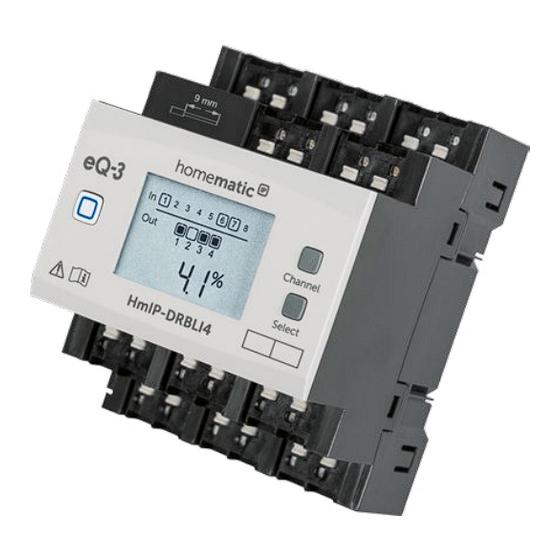
Funktion und Geräteübersicht Funktion und Geräteübersicht Der Homematic IP Jalousieaktor – 4-fach lässt sich ein- fach auf einer Hutschiene in einem Stromkreisverteiler montieren. Einmal installiert, steuert er angeschlossene Jalousien, Rollläden oder Markisen über vier potential- freie, unabhängige Kanäle. Der Jalousieaktor ermöglicht eine komfortable Steuerung angeschlossener Jalousie-, Rollladen- bzw. - Page 19 Funktion und Geräteübersicht Displayübersicht (s. Abbildung 1): Symbol Bedeutung Kanal eingeschaltet Kanal ausgeschaltet Eingang nicht betätigt Eingang betätigt Daten werden empfangen Daten werden gesendet Höhe der Jalousie bzw. des Rollladens am ausgewählten Kanal Lamellenposition der Jalousie am ausgewählten Kanal Prozentangabe (eingeschaltet, wenn die Höhe, Lamellenposition oder Duty-Cycle angezeigt wird) Temperaturangabe (eingeschaltet, wenn...
-
Page 20: Allgemeine Systeminformationen
Allgemeine Systeminformationen Allgemeine Systeminformationen Dieses Gerät ist Teil des Homematic IP Smart-Home- Systems und kommuniziert über das Homematic IP Funkprotokoll. Alle Geräte des Systems können komfor- tabel und individuell per Smartphone über die Home- matic IP App konfiguriert werden. Alternativ haben Sie die Möglichkeit, Homematic ... - Page 21 Inbetriebnahme Durch eine unsachgemäße Installation gefährden Sie • Ihr eigenes Leben; • das Leben der Nutzer der elektrischen Anlage. Mit einer unsachgemäßen Installation riskieren Sie schwere Sachschäden, z. B. durch Brand. Es droht für Sie die persönliche Haftung bei Personen- und Sachschäden. Wenden Sie sich an einen Elektroinstallateur! Erforderliche Fachkenntnisse für die Installation: Für die Installation sind insbesondere folgende Fachkenntnisse er-...
-
Page 22: Montage Und Installation
Inbetriebnahme Beachten Sie die auf dem Gerät angegebene Ab- isolierlänge der anzuschließenden Leiter. Zugelassene Leitungsquerschnitte zum Anschluss an den Jalousieaktor sind: Starre Leitung [mm Flexible Leitung ohne Aderendhülse [mm 0,75 – 2,50 0,75 – 2,50 Montage und Installation Bitte lesen Sie diesen Abschnitt erst vollständig, bevor Sie mit der Installation beginnen. - Page 23 Inbetriebnahme (s. Abbildung 4). • Verdrahten Sie das Gerät gemäß den Anschluss- zeichnungen in Abbildung 6 oder 7. • Schließen Sie zur Versorgung des Jalousieaktors den Neutralleiter an die Klemme K und den Au- ßenleiter an die Klemme J an (s. Abbildung 7). Es können beliebige Außenleiter (L1, L2, L3) ange- schlossen werden.
- Page 24 Inbetriebnahme Die Netzklemmen dürfen nur zum Anschluss der Netzspannung an das Gerät bzw. zum Anschluss von Verbrauchern an das Gerät verwendet wer- den. Das Weiterverbinden (Durchschleifen) von Leitern über die Netzklemmen des Geräts zu an- deren Geräten ist nicht erlaubt! •...
-
Page 25: Anlernen
Bitte lesen Sie diesen Abschnitt erst vollständig, bevor Sie mit dem Anlernen beginnen. Richten Sie zunächst Ihren Homematic IP Access Point über die Homematic IP App ein, um weitere Homematic IP Geräte im System nutzen zu kön- nen. Ausführliche Informationen dazu finden Sie in der Bedienungsanleitung des Access Points. - Page 26 Inbetriebnahme Sie können den Anlernmodus manuell für weitere 3 Minuten starten, indem Sie die Systemtaste (A) kurz drücken (s. Abbildung 9). • Das Gerät erscheint automatisch in der Home- matic IP App. • Zur Bestätigung geben Sie in der App die letzten vier Ziffern der Gerätenummer (SGTIN) ein oder scannen Sie den QR-Code.
-
Page 27: Bedienung
Bedienung Bedienung Über die folgenden Tasten stehen Ihnen einfache Bedien- funktionen direkt am Gerät zur Verfügung: Systemtaste (A) • • Channel-Taste (B) Select-Taste (C) • externe Taster/Schalter (H und L) • Systemtaste Durch kurzes Drücken der Systemtaste (s. Abbildung 10) können Sie die LCD-Hintergrundbeleuchtung aktivieren. - Page 28 Bedienung Symbol Bedeutung Runterfahren Hochfahren Stopp Select-Taste Wenn Sie über die Channel-Taste einen Kanal ausge- wählt haben (s. Channel-Taste), können Sie durch kurzes Drücken der Select-Taste (s. Abbildung 12) den Zustand des Ausgangskanals (Runterfahren - Stopp - Hochfahren - Stopp usw.) auswählen. Bei jeder Betätigung wird ein Zustand weiter geschaltet.
- Page 29 Bedienung Externe Taster/Schalter Mit den externen Tastern/Schaltern kann jeder Kanal di- rekt rauf- bzw. runterfahren werden. Taster: • Kurzer Tastendruck Taste für Kanal 1, 3, 5, 7: Der Motor für die Rollläden oder die Markise fährt bis zur Endposition runter. •...
-
Page 30: Fehlerbehebung
Fehlerbehebung Fehlerbehebung Fehlercodes und Blinkfolgen Blinkcode/ Bedeutung Lösung LCD-Anzeige Kurzes oranges Anlernmodus Geben Sie die Blinken (alle aktiv letzten vier Ziffern 10 s) der Geräte- Seriennummer zur Bestätigung ein (s. „5.3 Anlernen“ auf Seite 25). 6x langes rotes Gerät defekt Achten Sie auf die Blinken Anzeige in Ihrer... -
Page 31: Befehl Nicht Bestätigt
Erreichen des 1 %-Limits nicht mehr senden, bis diese zeitliche Begrenzung vorüber ist. Gemäß dieser Richtlinie, werden Homematic IP Geräte zu 100 % nor- menkonform entwickelt und produziert. Im normalen Betrieb wird der Duty Cycle in der Regel nicht erreicht. -
Page 32: Wiederherstellung Der Werkseinstellungen
Wiederherstellung der Werkseinstellungen Eine Überschreitung des Duty Cycle-Limits wird durch ein langes rotes Leuchten der LED (A) angezeigt und kann sich durch temporär fehlende Funktion des Geräts äußern. Nach kurzer Zeit (max. 1 Stunde) ist die Funktion des Geräts wiederhergestellt. Wiederherstellung der Werkseinstellungen Die Werkseinstellungen des Geräts können wie-... -
Page 33: Wartung Und Reinigung
Wartung und Reinigung Wartung und Reinigung Das Gerät ist wartungsfrei. Überlassen Sie eine War- tung oder Reparatur einer Fachkraft. Schalten Sie vor Ausbau des Geräts unbedingt die Netzspannung frei (Sicherungsautomat abschal- ten)! Arbeiten am 230 V-Netz dürfen nur von ei- ner Elektro-Fachkraft (nach VDE 0100) erfolgen. -
Page 34: Technische Daten
Technische Daten Hiermit erklärt die eQ-3 AG, Maiburger Str. 29, 26789 Leer, Deutschland, dass der Funkanlagentyp Home- matic IP HmIP-DRBLI4 der Richtlinie 2014/53/EU ent- spricht. Der vollständige Text der EU-Konformitätserklä- rung ist unter der folgenden Internetadresse verfügbar: www.homematic-ip.com Technische Daten Geräte-Kurzbezeichnung:... - Page 35 Technische Daten Abmessungen (B x H x T): 72 x 90 x 69 mm (4 TE) Gewicht: 256 g Funk-Frequenzband: 868,0-868,60 MHz 869,4-869,65 MHz Max. Funk-Sendeleistung: 10 dBm Empfängerkategorie: SRD category 2 Typ. Funk-Freifeldreichweite: 190 m Duty Cycle: < 1 % pro h/< 10 % pro h Technische Änderungen vorbehalten.
- Page 36 Package contents Quantity Description Blind Actuator for DIN rail mount – 4 channels User manual Documentation © 2019 eQ-3 AG, Germany All rights reserved. Translation from the original version in Ger- man. This manual may not be reproduced in any format, either in whole or in part, nor may it be duplicated or edited by electronic, mechanical or chemical means, without the written consent of the publisher.
- Page 37 Table of contents Information about this manual........38 Hazard information ............38 Function and device overview ........42 General system information ........44 Start-up ................45 Installation instructions ............. 45 Mounting and installation ..........46 Teaching-in ................49 Operation ................ 50 Troubleshooting .............54 Error codes and flashing sequences ......54 Command not confirmed ..........55 Duty cycle ................55 Restore factory settings ..........56...
-
Page 38: Information About This Manual
Information about this manual Please read this manual carefully before beginning op- eration with your Homematic IP component. Keep the manual so you can refer to it at a later date if you need to. If you hand over the device to other persons for use, hand over this manual as well. - Page 39 Hazard information Do not use the device if there are signs of dam- age to the housing, control elements or connect- ing sockets, for example. If you have any doubts, have the device checked by an expert. The device may only be operated in dry and dust- free environment and must be protected from the effects of moisture, vibrations, solar or other methods of heat radiation, cold and mechanical...
- Page 40 Hazard information qualified electricians (to VDE 0100) are permitted to carry out work on the 230 V mains. Applicable accident prevention regulations must be com- plied with whilst such work is being carried out. To avoid electric shocks from the device, please disconnect the mains voltage (trip the miniature circuit-breaker).
- Page 41 Hazard information The load current circuits have to be secured by a cable protection switch in accordance with EN60898-1 (tripping characteristic B or C, max. 10 A rated current, min. 6 kA interrupting rating, energy limiting class 3). For secure operation, the device has to be installed in a power distribution panel according to VDE 0603, DIN 43871 (low-voltage sub-distribution board), DIN 18015-x.
-
Page 42: Function And Device Overview
Function and device overview The Homematic IP Blind Actuator – 4 channels can be easily installed on a DIN rail within a distribution board. Once installed, the device controls connected blinds, shutters and awnings via four floating, independent channels. - Page 43 Function and device overview Device overview (see figure 1): A System button (teach-in/pairing button and LED) B Channel button C Select button D LC display E Connecting terminals for switched phase conductor for controlling the motor (“down”) F Connecting terminals for switched phase conductor for controlling the motor (“up”) G Connecting terminals for phase conductor H Connecting terminal for push-button/switch channel 2,...
-
Page 44: General System Information
General system information This device is part of the Homematic IP smart home sys- tem and works with the Homematic IP radio protocol. All devices of the system can be configured comfortably and individually with the Homematic IP smartphone app. Al-... -
Page 45: Start-Up
Start-up Start-up Installation instructions Before installation, please note the device num- ber (SGTIN) labelled on the device as well as the exact application purpose in order to make later allocation easier. You can also find the device number on the QR code sticker supplied. Please note! Only to be installed by persons with the relevant electro-technical knowledge and experience!*... -
Page 46: Mounting And Installation
Start-up sary, personal safety equipment; • Evaluation of measuring results; • Selection of electrical installation material for safeguard- ing shut-off conditions; • IP protection types; • Installation of electrical installation material; • Type of supply network (TN system, IT system, TT sys- tem) and the resulting connecting conditions (classical zero balancing, protective earthing, required additional measures etc.). - Page 47 Start-up • Disconnect the power distribution panel from the mains (see figure 2) and, if necessary, cover any live parts (see safety rules). • Remove the cover from the power distribution panel. • Place the blind actuator onto the DIN rail (see figure 3).
- Page 48 Start-up the blinds down for the selected channel to the corresponding terminal ( ) (E) (see figure 6+7). The phase conductor connection is marked with an arrow pointing to the centre of the device, the switched phase conductor with an arrow point- ing towards outside.
-
Page 49: Teaching-In
To integrate the device into your system and to enable control via the free Homematic IP app, you must teach-in the device to your Homematic IP Access Point first. To teach-in the device, please proceed as follows: •... -
Page 50: Operation
3 minutes by pressing the system button (A) briefly (see figure 9). • Your device will automatically appear in the Homematic IP app. • To confirm, enter the last four digits of the device number (SGTIN) in your app or scan the QR code. - Page 51 Operation Channel button (B) • • Select button (C) External push-buttons/switches (H and L) • System button By pressing the system button briefly (see figure 10), you can activate the LCD background light. Channel button By pressing the channel button briefly (see figure 11), you can select the desired channel.
- Page 52 Operation Symbol Meaning Move down Moved up Stop Select button After selecting a channel via the ‘Channel’ button, you can select the output channel status by briefly pressing the ‘Select’ button (see figure 12) (move down - stop - move up - stop etc.). On each button press, you can switch to the next status.
- Page 53 Operation Push-buttons: • Short button press button for channel 1, 3, 5, 7: The motor for the shutters/awnings moves down to the corresponding end position. • Short button press button for channel 2, 4, 6, 8: The motor for the shutters/awnings moves up to the corresponding end position.
-
Page 54: Troubleshooting
Troubleshooting Troubleshooting Error codes and flashing sequences Flashing code / Meaning Solution LC display Short orange Teach-in Enter the last four flashing (every mode active numbers of the 10 s) device serial number to confirm (see “5.3 Teaching-in” on page 49). 6x long red Device Have a look at... -
Page 55: Command Not Confirmed
Devices must cease transmission when they reach the 1% limit until this time restriction comes to an end. Homematic IP devices are designed and produced with 100% conformity to this regulation. During normal operation, the duty cycle is not usually reached. -
Page 56: Restore Factory Settings
Restore factory settings red lighting of the device LED (A) , and may manifest itself in the device temporarily working incorrectly. The device starts working correctly again after a short period (max. 1 hour). Restore factory settings The factory settings of the device can be restored. If you do this, you will lose all your settings. -
Page 57: Maintenance And Cleaning
Maintenance and cleaning Maintenance and cleaning The product does not require any maintenance. Enlist the help of an expert to carry out any main- tenance or repairs. The mains voltage must be disconnected before the device is removed (trip the miniature circuit- breaker). -
Page 58: Technical Specifications
Hereby, eQ-3 AG, Maiburger Str. 29, 26789 Leer/Germany declares that the radio equipment type Homematic IP HmIP-DRBLI4 is in compliance with Directive 2014/53/ EU. The full text of the EU declaration of conformity available following... - Page 59 Technical specifications 0.75-2.5 mm² Installation: mounting rail (DIN rail) according to EN 60715 Degree of protection: IP20 Ambient temperature: -5 to +40 °C Dimensions (W x H x D): 72 x 90 x 69 mm (4 WM width) Weight: 256 g Radio frequency band: 868.0-868.60 MHz 869.4-869.65 MHz...
- Page 60 Technical specifications Instructions for disposal Do not dispose of the device with regular domes- tic waste! Electronic equipment must be dis- posed of at local collection points for waste elec- tronic equipment in compliance with the Waste Electrical and Electronic Equipment Directive. Information about conformity The CE sign is a free trading sign addressed ex- clusively to the authorities and does not include...
- Page 61 Kostenloser Download der Homematic IP App! Free download of the Homematic IP app! Bevollmächtigter des Herstellers: Manufacturer’s authorised representative: eQ-3 AG Maiburger Straße 29 26789 Leer / GERMANY www.eQ-3.de...
Need help?
Do you have a question about the HmIP-DRBLI4 and is the answer not in the manual?
Questions and answers