BMC RESmart Service Manual
Cpap and autocpap system
Hide thumbs
Also See for RESmart:
- Service manual (26 pages) ,
- User manual (6 pages) ,
- Service manual (26 pages)
Advertisement
Table of Contents
Advertisement
Table of Contents

Subscribe to Our Youtube Channel
Related Manuals for BMC RESmart


Summary of Contents for BMC RESmart
- Page 1 RESmart CPAP and AutoCPAP System ® Service Manual...
-
Page 2: Table Of Contents
Service Manual for RESmart CPAP and AutoCPAP V1.5 ® Table of Contents 1. Introduction ..........3 2. -
Page 3: Introduction
Service Manual for RESmart CPAP and AutoCPAP V1.5 ® 1. Introduction The RESmart CPAP / Auto-CPAP units are continuous ® positive airway pressure devices designed for the treatment of adult obstructive sleep apnea (OSA) only. This service manual is intended only for manufacturer authorized service personnel. -
Page 4: Structure
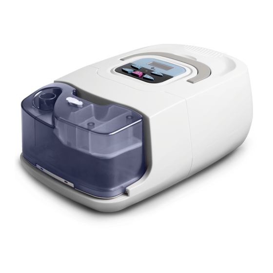
Service Manual for RESmart CPAP and AutoCPAP V1.5 ® 2. Structure 2.1 Outer Illumination Handle Medical DisplayScreen Product Note User Buttons (bottom) Humidifier AC Inlet Controller SD Card Air Outlet Humidifier Filter Cap Power & Filter Outlet Port Indicator Light... -
Page 5: Software
1. Request copy of upgrade file prior to starting your upgrade, copy on to new SD card. 2. Power off RESmart® CPAP/AutoCPAP device, then insert new SD Card. 3. Press and hold both Pressure Start/Stop Button and User Button (-). Plug in power cord while keeping both buttons pressed. -
Page 6: Hidden Function
1. Clearing Patient Data (Available on version 1.28 and later) Clearing the data of the RESmart CPAP and Auto-CPAP unit requires use of a hidden function. Caution: Once the data is cleared, there is no possibility of recovering erased data. - Page 7 Service Manual for RESmart CPAP and AutoCPAP V1.5 ® 2. Pressure calibration (Available on version 1.20 and later) Connect pressure meter to the gas outlet in the device, enter hidden datesetting, set ‘YYYY/MM/DD’=’2098/08/08’, press ‘On/Off’ when ‘Hour’ setting, thus pressure calibration starts. The device increases pressure to 20hPa(cmH2O), AD sampling data will appear on LCD.
-
Page 8: Malfunction And Countermeasure
Service Manual for RESmart CPAP and AutoCPAP V1.5 ® 4. Malfunction and Countermeasure 4.1 Malfunction Determination... -
Page 9: Error List And Information
Service Manual for RESmart CPAP and AutoCPAP V1.5 ® 4.2 Error List and Information Error Index Problem Causing Overheat Error reading from temperature sensor. Possible temperature sensor damage. Reset device if singular occurrence. Blower feedback error Check blower and pressure sensor. -
Page 10: Appendices
Service Manual for RESmart CPAP and AutoCPAP V1.5 ® Appendices Appendix A: Device Configuration 1. Main device Fig. A - Main board (backside) Fig. B – Outlet (leftside) Hole #1, 2 and 3 in Fig. B, connect to sensor YL and LL via silicon rubber canal. - Page 11 Service Manual for RESmart CPAP and AutoCPAP V1.5 ® Fig. C – Power PCBA (front side) Fig. D – Wire connecting on power PCBA Sockets figuration Blue Brown AC Socket 3-pin plug Fig. E – Power supply connecting Orange Orange...
- Page 12 Service Manual for RESmart CPAP and AutoCPAP V1.5 ® Fig. F – Power supply to humidifier Connecting relationship: Table 2...
- Page 13 Service Manual for RESmart CPAP and AutoCPAP V1.5 ® 2. Humidifier Fig. G – Humidifier PCBA (back side) Fig. H – Power supply to humidifier...
- Page 14 Service Manual for RESmart CPAP and AutoCPAP V1.5 ® Fig. I – Heater PCBA 4-pin plug 3-pin plug Power Reed to Humidifer Heater PCBA Connecting relationship: Table 3...
- Page 15 Service Manual for RESmart CPAP and AutoCPAP V1.5 ® Components Illumination 1. Device Inside Assembly Figure Insert humidifier locker on the shield bottom. Orange Black Insert humidifier power supply reed on the shield bottom as per Fig. E and F.
- Page 16 Service Manual for RESmart CPAP and AutoCPAP V1.5 ® Assembly Figure Clean up the wire. Assembly power PCBA in the socket and connect all plugs. Clean up the wire. Connect outlet to blower connector, fix by clip. Connect blower to connector and fix by clip.
- Page 17 Service Manual for RESmart CPAP and AutoCPAP V1.5 ® Assembly Figure FCBA Fixing Pole Assembly the main board PCBA on fixing pole and make sure the clip clamps power PCBA. 1. As per Table 1, connect sensor YL to outlet by silicon rubber canal.
- Page 18 Service Manual for RESmart CPAP and AutoCPAP V1.5 ® Assembly Figure Assembly handle fixing to handle and fix by screw (4×3mm*8mm). Infrared Assembly the infrared window. Window Assembly and fix the panel. Put on the key button. Assembly shield cover on the...
- Page 19 Service Manual for RESmart CPAP and AutoCPAP V1.5 ® Assembly Figure Plug (up) Power Plug Put on all plugs if necessary (without humidifier). Plug (down) 2. Humidifier Assembly Figure Black Orange As per Fig. H, assembly the heater plane and wire. Fix them by screw (3mm*8mm).
- Page 20 Service Manual for RESmart CPAP and AutoCPAP V1.5 ® Assembly Figure Assembly the inner and outer shield. Fix on screw (M3*10mm). Screw...
- Page 21 Service Manual for RESmart CPAP and AutoCPAP V1.5 ® Appendix B: Spare Part Configuration Name Figure Shield Cover Handle Handle Fixing Shield Bottom Humidifier Clip Humidifier Locker Humidifier Fixing Filter Cover Shield Back...
- Page 22 Service Manual for RESmart CPAP and AutoCPAP V1.5 ® Name Figure Outlet PCBA Fixing Infrared Window Panel Humidifier Outer Shield Humidifier Inner Shield Light Window Pole Platelet Humidifier Power Plug Humidifier Plug (left-up) Humidifier Plug (left-down)
- Page 23 Service Manual for RESmart CPAP and AutoCPAP V1.5 ® Name Figure Humidifier Plug (right-up) Humidifier Plug (right-down) Device Pad Blower Connector Humidifier Inner Connector Key Button Humidifier Scaleboard Heater Plane Spring Button Spring...
- Page 24 Service Manual for RESmart CPAP and AutoCPAP V1.5 ® Spare Part List Part Name Unit Classify Main Board PCBA 20211261 PCBA Main Device Heater PCBA 20212-41 PCBA Humidifier Power Supply PCBA 20311101 PCBA Main Device Blower 40211 Assembly Main Device...
- Page 25 Service Manual for RESmart CPAP and AutoCPAP V1.5 ® Spare Part List (cont.) Part Name Unit Classify Humidifier Inner Connector 4012110901 Rubber Humidifier Screw-1 Screw Screw-2 Screw Sunk Screw Screw Main Device Filter Accessory Power Cord 33011101 Accessory...
- Page 26 Service Manual for RESmart CPAP and AutoCPAP V1.5 ® Limited Warranty 3B Medical, Inc. (hereafter ‘3B’) warrants that the RESmart CPAP ® and Auto-CPAP devices will be free of all defects in workmanship and materials, and will perform according to specifications, for a period of two (2) years from the date of sale of the device, and 90 days on any accessories.
Need help?
Do you have a question about the RESmart and is the answer not in the manual?
Questions and answers