Table of Contents
Advertisement
Advertisement
Table of Contents

Related Manuals for Minelab MDS-10


Summary of Contents for Minelab MDS-10
- Page 1 Dual Sensor Detector Operations Manual...
- Page 2 No part of this document may be used or reproduced by any means or by any process, in any form, without the prior written permission of the copyright owner Minelab Electronics Pty Ltd of 2 Second Avenue, Mawson Lakes SA 5095, Australia.
- Page 3 Dual Sensor Detector Operations Manual Item Number: 4901‑0295‑1...
-
Page 4: Table Of Contents
Contents System Overview Sensor Feedback Settings ��������������������25 Selecting Sensor Feedback Settings MDS‑10 Overview �������������������������������������� 6 Visual Feedback Audio Feedback MDS‑10 Kit Contents ����������������������������������7 Vibration Feedback Standard Items Tactical Mode Optional Items User Interface Feedback MDS‑10 Main Detector Parts ������������������ 8 Detector Audio ������������������������������������������... - Page 5 GPR Skyshot ���������������������������������������������� 37 Interrogation Mode Procedure Parts of the Target ID Field GPR Sensor Calibration MD Target ID GPR Skyshot Procedure Target ID Examples GPR Sensitivity �����������������������������������������39 Setting the GPR Sensitivity Accessories Advanced GPR Settings �������������������������40 Detector Battery ��������������������������������������53 GPR Start/Stop Gates Battery Status Indicator Setting the Start/Stop Gates Low Battery Alert...
-
Page 6: System Overview
Unexploded ordnance • Landmines Dual Sensor Technology Ease of Use The MDS‑10 combines Minelab’s patented The User Interface features a versatile colour LCD Simultaneous Multi‑Frequency Digital technology screen and is designed for intuitive operation and and Chemring’s proven Ultra Wideband minimising Operator training requirements. -
Page 7: Mds-10 Kit Contents
MDS‑10 Kit Contents The MDS‑10 is supplied as a complete kit packed in a hard transit case for storage and transportation. Standard Items Optional Items 1. MDS‑10 Detector 10. AA Battery Pack 2. Hard Transit Case 11. Personal Role Radio Adapter Cable 3. -
Page 8: Main Detector Parts
MDS‑10 Main Detector Parts The major parts listed are referred to throughout this Operations Manual. 8 | System Overview... -
Page 9: Mds-10 Detector
MDS‑10 Detector Attachment Points Sturdy attachment points are located near the 1. Lithium‑ion Rechargeable Battery front of the control box. These are sized to fit 2. Battery Release Lever standard 25mm (1") webbing straps for 3. Control Box attachment to load carrying equipment. 4. -
Page 10: Operating Modes Overview
Operating Modes Overview The MDS‑10 has three main operating modes; Dual Sensor Mode, MD Mode, and GPR Mode. Dual Sensor Mode (Default) The following additional MD functions are also available in both MD Mode and Dual Sensor In Dual Sensor Mode, both MD and GPR Sensors Mode: are operational and provide detection feedback to the operator. -
Page 11: Additional Settings Overview
Additional Settings Overview The MDS‑10 has a Setup Screen accessible in all operating modes enabling the user to access more settings. Setup Screen Additional Functions and Settings The Setup Screen (page 18) is accessible from Dual Sensor Mode, MD Mode and GPR Mode by a The following additional functions and settings short‑press of the Setup Button (page 14). -
Page 12: 12 | Getting Started
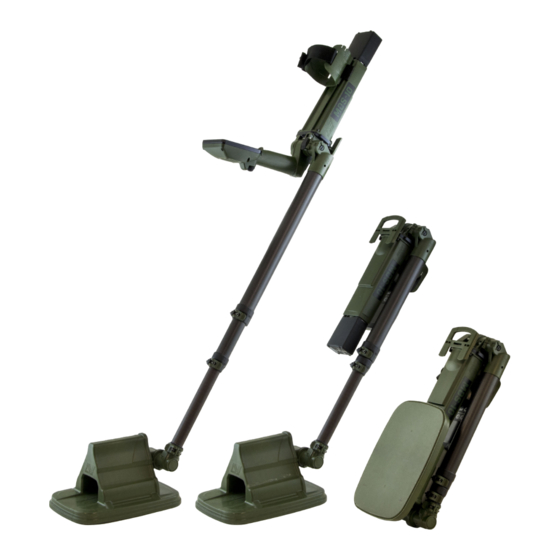
MDS‑10 Unfolding Procedure Follow these steps to unfold the MDS‑10 ready for operation. Before beginning, remove the detector from the protective hard‑case or carry bag. Extend the Lower Shaft 1. Open the lower shaft camlock. 2. Slide the lower shaft out to full extension. - Page 13 Extend the Middle Shaft 11. Open the upper shaft camlock. 12. Extend the middle shaft. 13. Close the upper shaft camlock. Attach Battery 14. Align the battery perpendicular to its final position. 15. Depress the Battery Lock Lever. 16. Rotate the battery 90 degrees, then release the lever.
-
Page 14: User Interface
User Interface The MDS‑10 User Interface has a large LCD Screen, a backlight, and a keypad. The User Interface displays and controls all of the detector functions. The Trigger button icon Additional Button Functions Main button function icon Some buttons are used for more than one function, indicated by a small icon adjoining the button. - Page 15 1. LCD 8. Plus Button Displays detector settings, options, and detection Short‑press from the Detect Screen to display and information (page 16). increase the detector Volume level (page 27). Short‑press at the same time as the Minus button to 2. MD Button enable Night Vision Mode (page 24).
-
Page 16: Lcd Screen
LCD Screen The MDS‑10 LCD displays detector settings, options, and represents target detections visually. Key screens include the Detect Screen, the Setup Screen, and the Pause Screen. Detect Screen The Detect Screen displays the real‑time detection information for enabled Sensors. Detect Screen in MD Mode Most MD information is displayed in the MD display area on the left side of the LCD. - Page 17 Parts of the Detect Screen The example below shows the Detect Screen with Factory Preset settings. By default, Dual Sensor Mode is enabled, therefore both MD (red) and GPR (yellow) functions and settings are displayed. 1. Status Bar 6. Enabled MD Feedback Indicators Displays quick‑reference information for the Indicates enabled MD Feedback settings;...
-
Page 18: Setup Screen
Setup Screen Short‑press the Setup button to display the Setup Screen. The example below shows the Setup Screen with Factory Preset settings. Parts of the Setup Screen 1. Settings Overview Area 9. MD Ground Balance Mode Displays the current detector settings. They Displays the current Ground Balance Mode cannot be adjusted from the Setup Screen. -
Page 19: Setup Pages
Setup Pages Within the Setup Screen, there are 3 Setup Pages: the General Setup Page, the MD Setup Page, and the GPR Setup Page. Each Page has different Soft Key Options at the bottom of the screen. The General Setup Page The General Setup Page displays the following Soft‑Key Options: Ground Balance Mode... -
Page 20: Quick Start
Quick Start Follow the Quick Start procedure to make the MDS‑10 ready for operation. Begin with an assembled detector (See MDS‑10 Unfolding Procedure on page 12.) Factory Reset Note: All detector modes and settings are saved Factory Reset will return all detector settings after the detector is powered Off, including after removal/replacement of the battery. - Page 21 4� MD Test Piece Carry out the MD Test Piece procedure (page 22) to confirm the MD Sensor is working correctly. 3� GPR Skyshot Ensure that the first GPR Target Indicator LED has stopped flashing. Carry out the GPR Skyshot Procedure (page 38). 2 3s Short-press 5�...
-
Page 22: Md Test Piece
MDS‑10 always be first tested with the supplied MD Test Piece before local test pieces are used for testing. The Minelab MDS-10 MD Test Piece MD Test Piece Procedure 1. Ensure that hands and arms are free of metallic objects (watches, rings etc.), and that no other... -
Page 23: Gpr Test Target
GPR mines or targets as test targets because they Sensitivity level is correct. represent the local threat. Minelab recommends that the detector always be first tested with the supplied GPR Test Target before local test targets are used for testing. -
Page 24: 24 | Settings Adjustment
LCD and LED Indicator Settings The LCD Screen and Target Indicator LEDs have a range of settings that allow the Operator to detect in high and low light situations. LCD and LED Brightness Turn the LCD On or Off 1. To turn the LCD On or Off, long‑press the Play/ The LCD is dual‑mode with a backlight for daytime use and Night Vision Mode for use with NVIS. -
Page 25: Sensor Feedback Settings
Sensor Feedback Settings Sensor Feedback upon target detection is provided via a combination of visual, audio, and tactile (vibration) responses. These combinations can be selected to suit the detecting application and user preference. The visual, audio, and tactile (vibration) Feedback Or, to display the GPR Setup Page, short‑press Settings for each sensor can be independently the GPR button. -
Page 26: Visual Feedback
Visual Feedback Tactical Mode Visual feedback is provided in the form of two LED Tactical Mode is provided as a quick means bar indicators that display a visual indication of of configuring the detector settings for use in MD and GPR received signal strength. tactical deployment situations. -
Page 27: Detector Audio
Detector Audio The MDS‑10 is compatible with a number of Audio accessories. Volume Speaker Auto‑Mute (Default) Speaker audio is automatically On if an The MDS‑10 has a single Volume control adjusting earset is not connected. Speaker audio is MD, GPR and user interface audio responses. automatically muted (Off ) if an earset is connected. -
Page 28: Mds-10 Earset Audio
MDS‑10 Earset Audio 3�5mm (1/8") Audio Adapter Cable The 3.5mm (1/8") adapter is an optional accessory The MDS‑10 earset has a unique connector that for connecting standard 3.5mm (1/8") headphones is compatible with the earset connector on the to the MDS‑10. control box. -
Page 29: Md Overview | 29
MD Sensor Overview The MD Sensor detects metal (conductive) objects. Enabling the MD Sensor The MD Sensor is enabled and disabled by long‑pressing the MD button. All MD related functions are colour coded red for quick recognition. When the MD Sensor is enabled, the MD Sensor Modes can be accessed. -
Page 30: Md Sensor Modes
MD Sensor Modes Detection Mode (Default) Pinpoint Mode can also be used to locate the centre of a target. For detailed information on Detection Mode is optimised for maximum locating the centre of a target using Pinpoint detection performance, and is the default MD Mode, read page 50. -
Page 31: Md Ground Balance
MD Ground Balance MD Ground Balance reduces noise caused by ground mineralisation, allowing targets to be detected more clearly. MD Sensor Calibration The MDS‑10 is capable of detecting metallic objects in all ground conditions. During the The MD Sensor calibration occurs for Ground Balance procedure, the detector learns approximately 5 seconds after the MDS‑10 is and adapts to the ground characteristics to... -
Page 32: Md Ground Balance Procedure
MD Ground Balance Procedure 3. Sweep the coil left and right across the metal target free ground, maintaining a sweep 1. Ensure this procedure is carried out on height of 25–50mm (1–2"). ground that contains no metal targets, and is representative of the ground in the intended search area. -
Page 33: Ground Balance Mode
The Conventional Mode behaves more like a conventional mine detector such The Ground Balance button as the Minelab F3. It is less sensitive to high frequency objects such as wires, carbon rods The Ground Balance Mode icon will change to and charcoal. -
Page 34: Md Noise Cancel
MD Noise Cancel MD Noise Cancel adjusts the MD Sensor to reduce electrical interference. 3. The Noise Cancel icon and progress bar will Detectors may become noisy due to electrical interference from power lines, electrical be shown on the LCD. A tone and/or vibration equipment, or other detectors operating nearby. -
Page 35: Md Sensitivity
MD Sensitivity MD Sensitivity should be adjusted as needed to reduce false alarms arising from difficult grounds. The MD Sensitivity setting has a range from 1 (low) to When viewing the Setup Pages or when adjusting 10 (high) with a default setting of 6. the MD Sensitivity, the sensitivity level is displayed as a vertical gauge. -
Page 36: 36 | Gpr Overview
GPR Sensor Overview The GPR Sensor is capable of detecting both metallic and non‑metallic targets as well as ground anomalies (clutter). Enabling the GPR Sensor The GPR Sensor is enabled and disabled by long‑pressing the GPR button. All GPR related functions are colour coded yellow for quick recognition. -
Page 37: Gpr Skyshot
GPR Skyshot Skyshot is a calibration to remove the GPR's own radar signature from the GPR system for clearer imagery and optimum detection performance. GPR Sensor Calibration The GPR Sensor requires a Skyshot procedure before each use, and cannot be operated and no The GPR Sensor calibration occurs for GPR Imagery (page 43) will be generated until approximately 15 seconds after the MDS‑10 is... -
Page 38: Gpr Skyshot Procedure
GPR Skyshot Procedure 4. The GPR Image should appear clean without any objects visible. If the GPR image is 1. Ensure that the GPR Sensor is enabled, then degraded or horizontal bands are present raise the Sensor Head high up in the air, away (when the detector is still raised), repeat from all objects. -
Page 39: Gpr Sensitivity
GPR Sensitivity GPR Sensitivity should be adjusted as needed to reduce false target signals in more difficult grounds. The GPR Sensitivity Level The GPR Sensitivity setting has a range from 1 (low) Indicator in the Status Bar to 10 (high) with a default setting of 6. When viewing the Setup Pages or when adjusting Increasing sensitivity will increase the likelihood the GPR Sensitivity, the sensitivity level is... -
Page 40: Advanced Gpr Settings
Advanced GPR Settings The advanced GPR settings allow fine tuning of the GPR detection capability. GPR Start/Stop Gates Setting the Start/Stop Gates 1. Ensure that the GPR Sensor is enabled, then The GPR Start/Stop Gate Function allows the Operator to mask detections from layers of long‑press the Skyshot button. -
Page 41: Gpr Detection Threshold
to targets and clutter at all depths, rather than proportionally increasing with depth, as GPR Sensitivity does. Adjusting GPR Detection Threshold 1. With the GPR Sensor enabled, long‑press the Skyshot button. Start Gate adjustment will be displayed. The Skyshot button 5. -
Page 42: Play/Pause
Play/Pause The GPR Imagery and/or MD Trace can be paused if an anomaly of interest is observed. This pauses the GPR Image and MD Trace (see page 29) so it can be scrutinised. It also disables the transmitters for both MD and GPR Sensors. -
Page 43: Gpr Imagery Overview
GPR Imagery Overview Understanding GPR Imagery is a learned skill. Below are the basic fundamentals of GPR imagery interpretation. The MDS‑10 has a unique visual representation of subsurface imagery. This allows the Operator to distinguish anomalies visually, as well as audibly. Visual interpretation is based on soil composition, size, shape and density of the anomaly. -
Page 44: Detection Gpr Imagery
Detection GPR Imagery Noisy GPR Imagery The GPR Image shows a typical detection. The GPR Image is noisy, making it difficult to identify true Anomalies are overlaid in red to facilitate recognition. target signals among the erratic detections. Note the straight horizontal bands in the image, including above the ground surface. -
Page 45: Common Ground Type Imagery
Common Ground Type Imagery Shallow target detected under a grass surface. Note the GPR Imagery detected over a surface layer of leaves and irregular surface response due to the grass surface. bark. Note the irregular surface response due to the leaves and bark in the surface layer. -
Page 46: 46 | Operating Procedures
Search Technique Using the correct search technique is crucial for optimum detecting. Search Speed The detector should be swept with a smooth even motion at a speed between 0.5 to 1 metre/sec (1.5' to 3'/ sec). If the detector is swept too fast or too slow small or deep targets may be missed. Search Overlap It is standard operating procedure to use a half coil overlap when sweeping, to ensure full ground coverage. -
Page 47: Locating The Target
Locating the Target Target location techniques narrow down the exact location of a target. Mapping the Target This procedure is effective for mapping targets with both GPR and MD enabled (in Detection Mapping a detected target is an important Mode). For the MD, there are additional procedure that will allow the Operator to techniques that can be used to locate metal immediately gain an impression of the... -
Page 48: Md Search Tips
MD Search Tips Sensor Head Orientation Pinpoint Mode Target Feedback Always approach targets to be located/mapped/ pinpointed with the long sides of the Sensor Head. Never use the back and front of the Sensor Head to approach a target, as the target may not be detected, or may be inaccurately located. -
Page 49: Md Edge Mapping Procedure
MD Edge Mapping Procedure 2. Move the Sensor Head to approach the target area from a variety of angles. The MD edge mapping procedure uses Pinpoint Mode to identify the outer edges of a metal target Do not use the short sides of the Sensor Head when only the MD Sensor is enabled. -
Page 50: Md Pinpointing Procedure
MD Pinpointing Procedure 2. Sweep the coil over the target. After the target edges have been mapped, the If the target contains metal, the MD audio MD Pinpointing procedure is carried out to response will increase to the maximum precisely determine the centre of the target. pitch when the sensor heard is immediately adjacent to the target centre. -
Page 51: Md Interrogation Mode
MD Interrogation Mode Interrogation Mode provides information regarding characteristics and composition of a target. When using the detector in Dual Sensor Mode, Audio feedback will change; Interrogation the separate MD and GPR signals may be used to Mode audio will vary in tone corresponding to differentiate targets of different types. -
Page 52: Parts Of The Target Id Field
MD Target ID Low conductivity targets usually have a Target ID of 0 or 1, and have characteristics consistent with MD Target ID represents the apparent carbon rods or small wires. These can be found in conductivity and likely composition of a target. particular types of IED threats. -
Page 53: Accessories | 53
AC power pack, and the AC power cable. Both EU and US status bar will flash rapidly. power cables are included with the MDS-10 . • If audio is enabled, there will a rapid high‑low‑ high‑low tone every 10 seconds. -
Page 54: Charging The Lithium-Ion Battery
Charging the Lithium‑ion Charge Status LEDs Battery The charge status LEDs display the current state of the battery. 1. Plug the power cord or AC power supply into the back of the charger, and the power cord into a wall outlet. Turn on the power outlet. Charge status LEDs and All of the charge status LEDs will illuminate the Condition button on... -
Page 55: Optional Aa Battery Carrier
Optional AA Battery Carrier 4. Re‑insert the AA battery carrier into the enclosure. The MDS‑10 includes an optional AA battery carrier that holds 16 × AA batteries. This provides a backup option in scenarios where there is no access to mains power for battery charger operation. -
Page 56: 56 | Troubleshooting, Safety, And Maintenance
Troubleshooting If the listed problems occur, perform the recommended actions first before reporting the detector as faulty. Before performing the recommended actions listed below, perform Factory Reset (page 61). Problem Recommended Action 1. Ensure that the battery is charged. Detector will not turn On 2. - Page 57 1. Close the affected camlock 2. Using a 3mm allen key (not included), adjust the camlock screw no more than a one‑quarter turn at a time. 90° Shaft camlocks too loose/tight 3. Check that the camlock opens and closes firmly and without the need for excessive force.
-
Page 58: Error Codes
Error Codes In the event of a hardware fault, the MDS‑10 will display an Error Code. Try the recommended actions first, before reporting the detector as faulty. The MDS‑10 has a Built‑in Test (BIT) capability for Critical System Errors are indicated by the error identifying faults that can occur in the detector. -
Page 59: Advisory Errors
User interface module Critical authentication failure Fatal Error Recommended Action: Battery type detection fault Critical 1. Ensure a fully‑charged, Minelab approved UIM configuration load failure Critical battery is fitted (the battery supplied with the detector). UIM settings load failure Advisory 2. -
Page 60: Md Error Codes
MD Error Codes GPR Error Codes MD Error Codes indicate a possible fault with the GPR Error Codes indicate a possible fault with the MD coil or MD coil cable in the Sensor Head, or GPR Sensor. the MD electronics in the control box. If a GPR fault occurs, the Error icon will appear on If an MD fault occurs, the error icon will appear the Detect Screen, adjacent to the GPR Sensor... -
Page 61: Factory Presets
Factory Presets The factory preset detector settings are the default and recommended base‑ settings for typical detecting operations. Factory Preset Settings Factory Reset Factory Reset will return all detector settings and Function Default Setting modes to factory preset values. Dual Sensor Mode Sensor Mode (MD and GPR) 1. -
Page 62: Safety Advice And Maintenance
Safety Advice and Maintenance The MDS‑10 is safe to transport, store and operate when handled with the due care. Safety hazards applicable to this equipment are identified below. Hazard Precaution The GPR and MD Sensors in the Sensor Head emit very low power magnetic fields and Radio Frequency (RF) energy. - Page 63 • Do not allow the lithium‑ion battery internal cells to fully discharge. (Note: batteries safety and advice may be safely operated until the MDS-10 shuts down due to low battery, without fully discharging the battery internal cells.) • Ensure batteries have at least a partial charge if prolonged storage is anticipated.
-
Page 64: Mds-10 Detector Specification
16 × Alkaline AA Batteries | Runtime: 2.25 hours (Dual Sensor Mode) * Although the MDS-10 can withstand immersion to a depth of 3 metres (10-feet) for short periods of time, it is NOT designed for use as an underwater detector. - Page 65 4s waterfall display of subsurface anomalies with target overlay GPR Imagery highlights. Minelab reserves the right to respond to ongoing technical progress by introducing changes in design, equipment and technical features at any time. For the most up‑to‑date specifications for MDS‑10, visit www.minelab.com.
- Page 66 Australia & Asia Pacific + 61 8 8238 0888 Europe & Russia +353 21 423 2352 North, South & Central America +1 630 401 8150 Middle East & Africa +971 4 254 9995 countermine@minelab.com.au Part Number: 4901‑0295...
Need help?
Do you have a question about the MDS-10 and is the answer not in the manual?
Questions and answers