Sign In
Upload
Manuals
Brands
Dover Manuals
Industrial Equipment
OPW SiteSentinel Integra 100
Dover OPW SiteSentinel Integra 100 Manuals
Manuals and User Guides for Dover OPW SiteSentinel Integra 100. We have
1
Dover OPW SiteSentinel Integra 100 manual available for free PDF download: Installation Manual
Dover OPW SiteSentinel Integra 100 Installation Manual (101 pages)
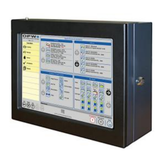
Automatic Tank Gauge System
Brand:
Dover
| Category:
Industrial Equipment
| Size: 4 MB
Table of Contents
Table of Contents
3
1 Applicable Warnings and Cautions
8
Technican Certifications
8
Installer Safety
8
Precision Leak Test
9
Prior to Initial Inspection
9
Initial Inspection
9
2 Sitesentinel Integra™ ATG Console
10
Blank Door Unit (Only for Integra 500)
10
Console Specifications
11
Console Installation
11
Console Wiring
13
Petro-Net™ Wiring (Only for Integra 500)
13
Wireless Connections (Only for Integra 500)
13
Ethernet Connections to Vsmart (Only for Integra 500)
13
Communications Conduits
14
Wireless Petro-Net Installation with Vsmart Indoors
15
Petro-Net over Ethernet Option with Vsmart
16
Field Wiring Diagram for Integra 100
18
Field Wiring Diagram for Integra 500
20
Console Board Inputs
22
Main Board DIP-Switch Configuration
23
3 External Printer
24
4 Vsmart Module (Only for Integra 500)
26
Vsmart Specifications
26
Vsmart Module Installation
27
Probe & Sensor Conduits
27
Circuit Breaker Conduits
27
External Vsmart Module Wiring
28
Vsmart Addressing
28
Vsmart Capabilies
29
5 Line Interface Module LIM (Only for Integra 500)
30
LIM Specifications
30
LIM Installation
30
LIM Wiring
31
Variable Speed Control for FE Petro
32
Typical FE Petro Wiring Connections
32
Variable Speed Control Wiring for Red Jacket
33
Typical Red Jacket Wiring Connections
33
LIM Addressing
33
6 OM4 Module (Only for Integra 500)
34
Cautions
34
OM4 Specifications
35
OM4 Wiring
35
OM4 Addressing
35
7 Tank Alert (Overfill Alarm)
36
Tank Alert Wiring
36
8 Tank & Pre-Installation Preparation
37
Waterproof Electrical Connections
37
Probe-Cable Seal-Offs
38
Probe Placement
39
Probe Installation in Underground Storage Tanks
40
Calculating Product Offset
41
9 Rigid Probe Installation
42
Adaptor Collar & Riser Cap
42
Probe Floats
42
Multi-Drop Installation
42
Rigid Probe Specification
43
Model 924B Probe
44
Model 924B Specifications
44
10 Flex Probe Installation
46
Model 7100V Flex Probe (Only for Integra 500)
46
Model 7100V Flex Probe Specifications
46
Flex Probe Installation
47
Flex Probe Length Determination
47
Flex Probe Installation Preparations
47
Flex Probe Determination Worksheet
48
Flex Probe Wiring
49
Installing the Flex Probe
49
Finishing the Flex Probe Installation
49
11 Model 327 Volumetric Line Leak Detector (VLLD) Sensor (Only for Integra 500)
50
VLLD Specifications
50
Prior to Installation
50
VLLD Installation
51
VLLD Wiring
53
12 Sensor Technology Overview
54
OPW Smart Sensors
54
Intellisense™ Technology
54
Multi-Drop Installation
54
Interstitial Sensor
55
Interstitial Sensor Installation
55
Wet Well Monitoring, Single-Wall Tank
56
Appendix A: OPW Smart Sensors
57
Interstitial Level Sensor Float Switch
57
Single-Level Sump Sensor
58
Single-Level Sump Sensor Installation
58
Liquid-Only Float Sensor
59
Liquid-Only Float Sensor Installation
59
Discriminating Dispenser Pan Sensor
60
Discriminating Dispenser Pan Sensor Installation
60
Discriminating STP Sump Sensor
61
Discriminating STP Sump Sensor Installation
61
Hydrocarbon Vapor Sensor
62
Hydrocarbon Vapor Sensor Installation
62
Discriminating Interstitial Sensor
63
Discriminating Interstitial Sensor Installation
63
Interstitial Hydrocarbon Liquid Sensor with Water Indicator
64
Hydrocarbon Liquid Sensor with Water Indicator
65
Dual-Float Dispenser Sump Sensor
66
Dual-Float STP Sump Sensor
67
Dual-Float Brine Sensors
68
Dual-Float Brine Sensor (D-10)
68
Dual-Float Brine Sensor (D-20B)
69
Universal Reservoir Sensor
70
Density Measurement Sensor (DMS)
71
DMS Installation
72
Tank Thresholds
72
DMS Configuration & Preliminary Calibration
72
Appendix B: Existing OPW/EECO Equipment
73
Model 924A Probes
73
Model EECO Probes
74
Appendix C: Smart Module (Only for Integra 500)
75
Appendix D: Maintenance Kit
76
Appendix E: Model 924B Probe Part Numbers
77
Appendix F: Output Relay Installation Report
78
Appendix G: Sensor Labels
80
Appendix H: Model 924B Installation Records
83
Appendix J: Flex Probe Specifications
84
Appendix K: 7100V Flex Probe Installation Records
87
Appendix L: Non-Smart Sensors (Only for Integra 500)
88
Hydrocarbon Liquid/Water Sensor
88
Hydrocarbon Vapor Sensor
89
Hydrocarbon Vapor Sensor Installation
89
Combo Single-Level / Hydrocarbon Liquid Sump Sensor
91
Combo Dual-Level/Hydrocarbon Liquid Sump Sensor
92
Single-Level Sump Sensor
94
Dual-Level Reservoir Sensor
95
Hydrocarbon Liquid Sump Sensor
96
Interstitial Optical Liquid Sensor
98
Appendix M: Declaration of Conformity
99
Index
101
Advertisement
Advertisement
Related Products
Dover OPW SiteSentinel Integra 500
Dover NORRISEAL 1001 Series
Dover NORRISEAL 1001A Series
Dover NORRISEAL 1001XL Series
Dover Blackmer TYPHON 1000
Dover Anthony Complete 101 Series
Dover Anthony Complete 103 Series
Dover Anthony Complete 101N
Dover Anthony Complete 103N
Dover Anthony Complete 103T
Dover Categories
Water Pump
Industrial Equipment
Dispenser
Printer
Garbage Disposal
More Dover Manuals
Login
Sign In
OR
Sign in with Facebook
Sign in with Google
Upload manual
Upload from disk
Upload from URL