Table of Contents
Advertisement
Quick Links
Advertisement
Table of Contents

Subscribe to Our Youtube Channel
Related Manuals for PR Lighting CSL 1037


Summary of Contents for PR Lighting CSL 1037
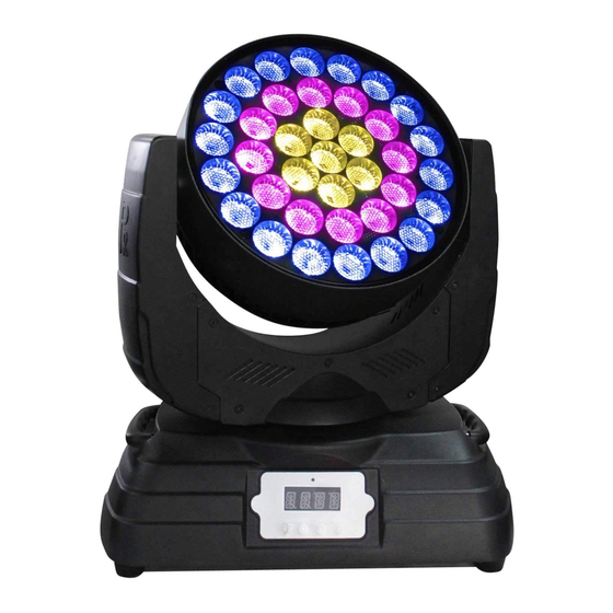
- Page 1 CSL 1037 PR-3206D This product manual contains important information about the safe installation and use of this unit. Please read and follow these instructions carefully and keep this manual in a safe place for future reference. PR LIGHTING LTD. http://www.pr-lighting.com...
-
Page 2: Table Of Contents
INDEX SAFE USAGE OF THE UNIT INSTALLING THE UNIT POWER SUPPLY-MAINS CONTROL CONNECTION DMX TERMINATOR SETUP OPTIONS-UNIT CONFIGURATION TO SET THE DMX START ADDRESS OPERATION MENU DMX PROTOCOL MAINTENANCE TROUBLESHOOTING TECHNICAL DATA ELECTRICAL DIAGRAM COMPONENT ORDER CODES Please note that as part of our ongoing commitment to continuous product development, specifications are subject to change without notice. -
Page 3: Safe Usage Of The Unit
SAFE US SAGE OF THE UNI When unpac cking and befor re disposing of f the carton, che eck there is no t transportation d damage before using the unit. Should there b any damage caused by trans sportation, cons sult your dealer and do not use the apparatus. -
Page 4: Installing The Unit
INSTALL THE UNIT Safety Cord Clamp Barn Door Knob The fixture works while being hung. Its head can be manually rotated with the range of 240 degrees. Before moving the head, loosen the two angle-knobs. After the head is at the angle desired, tighten the two knobs. Take 1 clamp and 1 safety cord out from the package and mount 1 clamp on the axis of the support with 1 retainer. -
Page 5: Power Supply-Mains
POWER SUPPLY-MAINS Connect the power cord as follows: L (live) =brown E (earth) =yellow/green N (neutral) =blue Before connection with mains power, make sure that the voltage and frequency marked on the rating plate of the projector match what are supplied. It is recommended that each projector be supplied separately so that they may be individually switched on and off. Note: If some fixtures are connected in series via POWER INs and POWER OUTs, connect the POWER IN of the first fixture with external power and connect its POWER OUT with the POWER IN of the second fixture and so on till all the fixtures are connected. -
Page 6: Control Connection
CONTROL CONNECTION DMX OUT DMX IN DMX 512 FUNCTION 5 PIN DATA- DATA+ Connection between the controller and a unit and between one unit and another must be made with a 2 core-screened cable, with each core having at least a 0.5mm diameter. Please use the unit’s cannon 5- pin signal input and output cables as connection. The 5-pin signal connections are connected as shown in the figure above. -
Page 7: Dmx Terminator
DMX TERMINATOR In the Controller mode, at the last fixture in the chain, the DMX output has to be connected with a DMX terminator. This prevents electrical noise from disturbing and corrupting the DMX control signals. The DMX terminator is simply an XLR connector with a 120Ω (ohm) resistor connected across pins 2 and 3, which is then plugged into the output socket on the last unit in the chain. -
Page 8: To Set The Dmx Start Address
TO SET THE DMX START ADDRESS Each unit must be given a DMX start address so that the correct unit responds to the correct control signals. This DMX start address is the channel number from which the unit starts to “listen” to the digital control information being sent out from the controller. The unit has 2 DMX channels, so set the No. -
Page 9: Maintenance
MAINTENANCE To prolong the life of the unit, it is very important to do the maintenance work. I f the unit is idle for a long time, damp, smoke or particularly dirty surroundings can cause greater accumulation of dirt on its cover and housing. So it should be cleaned to maintain an optimum light output and at the same time to prevent it from being corrupted by acid gas. -
Page 10: Technical Data
TECHNICAL DATA VOLTAGES: 100V~240V AC,50/60Hz POWER CONSUMPTION: 330@220V LED: Power consumption 37pcs Quantity 5600K Ra≥70 Manufacturers Rated LED Life 50000 Hours DIMMER: 0-100% linearly adjustable STROBE: Electronic Strobe,0.3-20 F.P.S BEAM ANGLE: Field Angle ( θ peak) 14.7° CONTROL: DMX512, 5pin interfaces 2Channels OTHE FUNCTIONS: Display of fixture’s hours... - Page 11 SIZES: Light Output 13887 3472 1543 14.7°(1/2)lux DISTANCE(m) 14.7°DIAMETER(m) 5.21 6.51 7.81 11/14...
-
Page 12: Electrical Diagram
ELECTRICAL DIAGRAM 12/14... -
Page 13: Component Order Codes
COMPONENT ORDER CODES NAME PART NO. QUANTITY REMARK 070070056 15° LED LAMPS’ LENS 150020297 LED LAMP 192010195 POWER SWTICH 230060441 LED LAMP PCB 230060437 LED DRIVER BOARD 230060435 CONTRAL BOARD 030060101 ¢95X25 242810033 XLR CALBE 120080012 1.5M POWER CORD 13/14... - Page 14 PR LIGHTING LTD. PR New Hi-tech Science Park, 1582 Xingye Avenue Nancun Panyu, Guangzhou, 511442 China TEL: +86-20-3995 2888 FAX: +86-20-3995 2330 P/N:320020306 Version: 20150615 14/14...
Need help?
Do you have a question about the CSL 1037 and is the answer not in the manual?
Questions and answers