Emerson Rosemount 928 Reference Manual
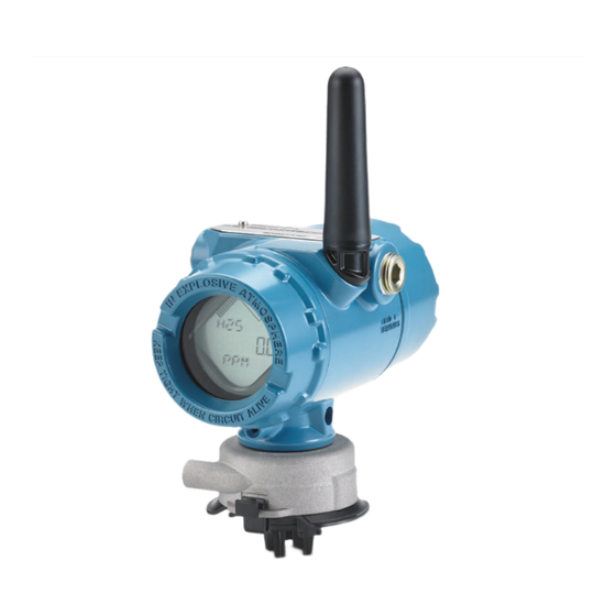
Wireless gas monitor
Hide thumbs
Also See for Rosemount 928:
- Reference manual (196 pages) ,
- Quick start manual (86 pages) ,
- Quick start manual (72 pages)

Related Manuals for Emerson Rosemount 928


Summary of Contents for Emerson Rosemount 928
- Page 1 Reference Manual 00809-0100-4928, Rev AE September 2019 ™ Rosemount 928 Wireless Gas Monitor...
- Page 2 Intrinsically Safe or non-incendive field wiring practices. When connecting an external device to the Rosemount 928's discrete output in a hazardous area, ensure that the external device is installed in accordance with Intrinsically Safe or non-incendive field wiring practices.
- Page 3 Installation problems Only install the Rosemount 928 and all other wireless devices after the Wireless Gateway has been installed and is functioning properly. Power up wireless devices in order of proximity from the Wireless Gateway, beginning with the closest. This will result in a simpler and faster network installation.
-
Page 5: Table Of Contents
4.3 Using Field Communicator to change the network ID and join key..........124 4.4 Using AMS Wireless Configurator to change the network ID and join key........124 4.5 Verify operation........................... 124 4.6 If there is an immediate alarm...................... 126 4.7 Troubleshoot communication...................... 126 Chapter 5 Operation and maintenance..................127 Rosemount 928... - Page 6 B.5 Installing in North America......................187 B.6 USA.............................. 187 B.7 Canada............................188 B.8 Europe............................189 B.9 International..........................190 B.10 China............................190 B.11 Japan............................190 B.12 Brazil............................191 B.13 Intrinsically Safe installation drawing..................192 Appendix C High gain remote antenna option................193 C.1 Safety messages...........................193 Emerson.com/Rosemount...
- Page 7 September 2019 C.2 Antenna functional specifications....................193 C.3 Installation considerations......................194 C.4 Transient and lightning considerations..................195 C.5 Dimensional drawing........................196 C.6 Install the high gain remote antenna.................... 197 Appendix D Alert message mapping....................201 D.1 Variable mapping.........................201 D.2 Alert mapping..........................201 Rosemount 928...
- Page 8 Contents Reference Manual September 2019 00809-0100-4928 viii Emerson.com/Rosemount...
-
Page 9: Chapter 1 Introduction
This manual covers the following modules • Rosemount 928XSS00 Wireless Gas Monitor — Ships with a separately specified Rosemount 628 Universal Gas Sensor. • Rosemount 928UTX00 Wireless Gas Monitor — Ships without a Rosemount 628 Universal Gas Sensor. Rosemount 928... -
Page 10: Device Overview
Ships without a Rosemount 628 Universal Gas Sensor. Device overview The Rosemount 928 Wireless Gas Monitor uses the Rosemount 628 Universal Gas Sensor to monitor the presence of toxic gases. The Rosemount 628 Universal Gas Sensor consists of an electrochemical sensor inside a hot-swappable sensor module installed into the transmitter housing. -
Page 11: Chapter 2 Configuration
The surface resistivity of the antenna is greater than one gigaohm. To avoid electrostatic charge buildup, do not rub or clean the antenna with solvents or a dry cloth. Substitution of components may impair intrinsic safety. Rosemount 928... -
Page 12: Install The Sensor
C. Filter media Note Use Rosemount 628 Universal Gas Sensors only with the Rosemount 928 Transmitter. The sensor is held in place using a tight-fitting seal and snap connections. The sensor is connected to the transmitter by two latching tabs that fit into the bottom portion of the... - Page 13 During the warm up period, the displayed values, alerts, and gas concentrations do not reflect actual measurements; readings are not transmitted. Table 2-1: Maximum Warm up Periods Gas type Maximum warm up period Hydrogen sulfide (H One minute Rosemount 928...
-
Page 14: Install The Power Module
To remove the sensor, compress the two latching tabs and pull downward until the module is released from the transmitter housing. Install the power module ™ The transmitter is powered by the Emerson 701 SmartPower Module - Black. To connect the module to the transmitter, do the following: Procedure 1. -
Page 15: Bench Configuration
To connect to the transmitter using a handheld communication device, refer to Guided setup. To obtain the latest DD, go to EmersonProcess.com/DeviceFiles and then visit the Emerson web page for your handheld device. Procedure 1. On the Home screen, select Configure. Rosemount 928... - Page 16 AMS Wireless Configurator is capable of connecting to devices directly, using a HART modem, or though a Wireless Gateway. Procedure 1. In the AMS Device Manager pane, select the HART modem. 2. In the device pane, double-click the device icon. 3. Select Configure. Emerson.com/Rosemount...
-
Page 17: Hart ® Menu Trees
The following figures show the navigation paths for Field Communicator commands and options. A Rosemount 928 Wireless Gas Monitor DD is required for HART Wireless transmitter communication. To obtain the latest Emerson DD, visit the System Software and Device Description web page for your handheld communicator device. Refer to the reference manual for your handheld communicator device. - Page 18 Configuration Reference Manual September 2019 00809-0100-4928 Figure 2-3: Field Communicator Overview Menu Tree Emerson.com/Rosemount...
- Page 19 Reference Manual Configuration 00809-0100-4928 September 2019 Figure 2-4: Field Communicator Configure Menu Tree Rosemount 928...
-
Page 20: Guided Setup
Guided setup Guided setup contains basic configurations settings. The Guided Setup menus are useful during initial configuration. Note Emerson developed the Field Communicator Guided Setup configuration procedures ™ using Emerson AMS Trex Device Communicator. The menus are identical to those found in other Field Communicators, but are navigated using touch screens rather than fast keys. - Page 21 3. Start your handheld communicator device. If necessary, open the HART Field Communicator application on your handheld device to establish HART communication. Refer to the manual for your handheld communicator device for more information. 4. On the Overview screen, select Configure. Rosemount 928...
- Page 22 6. Perform each of the configuration tasks in the following subsections. 2.7.1 Basic setup Basic setup using Field Communicator Procedure 1. On the Guided Setup screen, select Basic Setup. 2. On the Device Information screen, select any of the following and configure as needed. Otherwise, continue with Step Emerson.com/Rosemount...
- Page 23 The Long tag field is blank by default and does not display if left blank. • Tag: Enter an identifier for the device up to eight uppercase alphabetic and numeric characters long using the virtual keypad. The Tag field is blank by default and does not display if left blank. Rosemount 928...
- Page 24 The Descriptor field is blank by default and does not display if left blank. • Message: Enter a message up to 32 alphabetic, numeric, and special characters long. The Message field is blank by default, does not display if left blank, and may be used for any purpose. Emerson.com/Rosemount...
- Page 25 Reference Manual Configuration 00809-0100-4928 September 2019 3. On the Device Information screen, select Next. Rosemount 928...
- Page 26 September 2019 00809-0100-4928 4. On the Basic Setup screen, select OK to confirm successful completion of basic setup. Basic setup using AMS Wireless Configurator Procedure 1. On the Guided Setup tab, in the Initial Setup field, select Basic Setup. Emerson.com/Rosemount...
- Page 27 • Message: Enter a message up to 32 alphabetic, numeric, and special characters long. The Message field is left blank by default, does not display if left blank, and may be used for any purpose. Rosemount 928...
- Page 28 One new device joining an existing network with multiple devices may take up to five minutes. Multiple new devices joining an existing network may take up to 60 minutes. Emerson.com/Rosemount...
- Page 29 2. On the Join to Network screen, use the numeric keypad to enter the WirelessHART network ID. The network ID must match the Wireless Gateway network ID. Refer to the System Settings → Network → Network Settings page in the Wireless Gateway web-based user interface for the network ID. 3. Select OK. Rosemount 928...
- Page 30 6. Repeat Step 4 Step 5 for parts 2 - 4 of the join key. Join a wireless network using AMS Wireless Configurator Procedure 1. On the Guided Setup tab, in the Wireless field, select Join Device to Network. Emerson.com/Rosemount...
- Page 31 Consider the speed with which you want to be alerted to a dangerous condition of toxic gas. Emerson does not recommend reporting by exception for the Rosemount 928 Wireless Gas Monitors or Emerson Wireless Gateways due to its potential adverse effect on Wireless Gateway capacity and network integrity. Therefore, select an update rate for all wireless gas monitors that corresponds to the safety needs of your facility but does not exceed the capacity of the Wireless Gateway or your wireless network.
- Page 32 2.7.4 Configuring the update rate The Rosemount 928 takes measurements every two seconds. The update rate is the frequency at which new measurements and device statuses are transmitted over the wireless network. You may change the update rate during configuration. The update rate range is one second to sixty minutes.
- Page 33 Reference Manual Configuration 00809-0100-4928 September 2019 • a. For update rates greater than 60 seconds, select 61-3600 seconds from the list. b. Enter the update rate in number of seconds. For example, enter 1800 seconds for 30 minutes. Rosemount 928...
- Page 34 Reference Manual September 2019 00809-0100-4928 c. Select OK. 3. On the Emerson Wireless Gateway Optimizations screen, select Yes - Enable Optimizations to save and use wireless optimizations or select No - Disable Optimizations to reject wireless optimizations. Note Wireless gateway optimizations combine process measurement and device diagnostic messages from field devices to the wireless gateway, saving network bandwidth.
- Page 35 2. On the Configure Update Rate screen, do one of the following: • a. Select an update rate from 1 to 60 seconds from the list. b. Select Next. Rosemount 928...
- Page 36 Configuration Reference Manual September 2019 00809-0100-4928 • a. Select 61-3600 from the list. b. Type the number of seconds for an update rate from 61 seconds to 60 minutes. For example, enter 1800 seconds for 30 minutes. Emerson.com/Rosemount...
- Page 37 If you don't use optimizations, you will need more message packets to receive the same amount of information. Emerson recommends enabling wireless gateway optimizations unless they are incompatible with the wireless gateway.
- Page 38 Disabling the display mode or selecting a less frequent display mode extends power module life. Configure the device display mode using Field Communicator Procedure 1. On the Guided Setup screen, select Configure Device Display. Emerson.com/Rosemount...
- Page 39 When a handheld communication device is connected to the transmitter, the LCD display is in High Availability mode. Selecting and accepting the On Demand or Periodic options does not take effect until approximately five minutes after the handheld communicator device is disconnected. Selecting and displaying Disabled takes effect immediately. Rosemount 928...
- Page 40 AMS Device Manager status screen, on the Wireless Gateway web interface, on host systems with which the Wireless Gateway communicates, and in the error section of the LCD display (if so configured). Disable process alerts if the Rosemount 928 is not connected to a wireless network.
- Page 41 Refer to Clearing process alarm history. You may query alert history for other process alerts to determine whether they have been active. Configure process alerts using Field Communicator Procedure 1. On the Guided Setup screen, select Configure Process Alerts. Rosemount 928...
- Page 42 Configuration Reference Manual September 2019 00809-0100-4928 2. On the Process Alerts screen, select a process alert to configure. 3. On the selected process alert screen, select Mode. Emerson.com/Rosemount...
- Page 43 Reference Manual Configuration 00809-0100-4928 September 2019 4. On the Mode screen, select Enabled. 5. Select OK. 6. On the selected process alert screen, select Alert Limit. Rosemount 928...
- Page 44 7. On the Alert Limit screen, use the numeric keypad to enter an alert limit for the selected process alert based on your needs and local regulations. 8. Select OK. 9. On the selected process alert screen, select Next. Emerson.com/Rosemount...
- Page 45 Comm terminals on the terminal block and replace the rear housing cover. Configure process alerts using AMS Wireless Configurator Procedure 1. On the Guided Setup tab, in the Optional Setup field, select Configure Process Alerts. The Process Alerts window is displayed. Rosemount 928...
- Page 46 3. In the Alert Limit box, enter an alert limit for the selected process alert based on your needs and local regulations. 4. Repeat Step 2 Step 3 if necessary to configure the Hi Alarm process alert. 5. Select Next. Emerson.com/Rosemount...
-
Page 47: Calibrating The Sensor
Calibrating the sensor Calibrating the sensor ensures that the analog, digital, and discrete outputs accurately transmit the target gas concentrations registered by the module. Although Emerson calibrated the device at the factory, you must calibrate it at the following times to ensure accuracy and correct operation: •... - Page 48 Note Emerson developed the Field Communicator guided setup configuration procedures in this manual using Emerson AMS Trex Device Communicator. The menus are identical to those found in other Field Communicators, but you navigate using touch screens rather than fast keys. Refer to the manual for your handheld communication device for more information.
- Page 49 Reference Manual Configuration 00809-0100-4928 September 2019 4. On the Configure screen, select Guided Setup. 5. On the Guided Setup screen, select Calibrate Sensor. Rosemount 928...
- Page 50 Obtain a cylinder of verified clean air (H S and CO) or a cylinder of verified percent oxygen content calibration gas (O ) and a length of calibration tubing (PVC tubing, 3/16-in. ID, 5/16-in. OD). Emerson.com/Rosemount...
- Page 51 Complete Step 9 through Step f) Turn off the clean air (or percent oxygen specified calibration gas) when the sensor is correctly zeroed. Rosemount 928...
- Page 52 Configuration Reference Manual September 2019 00809-0100-4928 9. Select OK when the zero measurement reading stabilizes. Note Negative measurement readings may occur and are normal during zeroing. 10. Wait while the Field Communicator performs zero adjustment. Emerson.com/Rosemount...
- Page 53 12. On the Calibrate Sensor screen, enter a gas concentration level that corresponds to the concentration of calibration gas that will be applied during calibration. For oxygen, use 20.9 percent oxygen from clean air. This step may be performed with surrounding air if no contaminants are present. 13. Select OK. Rosemount 928...
- Page 54 Install a regulator on the target gas source. 15. Attach a length of calibration tubing (PVC tubing, 3/16-in. ID, 5/16-in. OD) from the regulator on the target gas source to the fitting on the IP filter assembly (part number 00628-9000-0001). Emerson.com/Rosemount...
- Page 55 00809-0100-4928 September 2019 16. Release the target gas from the target gas source. Emerson recommends a flow rate of 1.0 liters per minute to ensure a consistent sensor reading. Note If you need a long length of tubing to reach the device, make allowances for a delay in response time from the sensor while the target gas travels the length of the calibration tubing.
- Page 56 IP filter is not clogged or obstructed. A sensor that cannot accept a new calibration may have reached the end of its service life. Replace the sensor and repeat this procedure. Refer to Replace the gas sensor. Emerson.com/Rosemount...
- Page 57 23. Shut off the target gas flow at the regulator. 24. Detach the calibration tubing from the regulator on the target gas source and from the IP filter inlet on the bottom of the sensor. Rosemount 928...
- Page 58 Configuration Reference Manual September 2019 00809-0100-4928 2.8.2 Calibrate using AMS Wireless Configurator Procedure 1. On the Guided Setup tab, in the Initial Setup field, select Calibrate Sensor. Emerson.com/Rosemount...
- Page 59 Reference Manual Configuration 00809-0100-4928 September 2019 2. On the Calibrate Sensor screen, select Next to accept the current date as the calibration date and continue. Rosemount 928...
- Page 60 Obtain a cylinder of verified clean air (H S and CO) or a cylinder of verified percent oxygen content calibration gas (O ) and a length of calibration tubing (PVC tubing, 3/16-in. ID, 5/16-in. OD). Emerson.com/Rosemount...
- Page 61 Perform Step 5 through Step f) Turn off the clean air/known percent oxygen specified calibration gas when the sensor is correctly zeroed. Rosemount 928...
- Page 62 Configuration Reference Manual September 2019 00809-0100-4928 5. Select Next when the zero measurement reading stabilizes. 6. Select Next. Emerson.com/Rosemount...
- Page 63 Reference Manual Configuration 00809-0100-4928 September 2019 7. Select Accept New Zero. 8. Select Next. Rosemount 928...
- Page 64 00809-0100-4928 9. On the Calibrate Sensor screen, enter a gas concentration level. 10. Select Next. WARNING Toxic gas The regulator may release gas into the air during calibration. Before starting the next step, verify that the regulator is closed. Emerson.com/Rosemount...
- Page 65 11. Install a regulator on the target gas source. 12. Attach a length of calibration tubing (PVC tubing, 3/16-in. ID, 5/16-in. OD) from the regulator on the target gas source to the IP filter inlet on the bottom of the sensor. Rosemount 928...
- Page 66 September 2019 00809-0100-4928 13. Release the target gas from the target gas source. Emerson recommends a flow rate of 1.0 liters per minute to ensure a consistent sensor reading. Note If you need a long length of calibration tubing to reach the device, make allowances for a delay in response time from the sensor while the target gas travels the length of the calibration tubing.
- Page 67 Reference Manual Configuration 00809-0100-4928 September 2019 15. Select Next when the gas concentration measurement stabilizes at or near the target gas concentration level. Rosemount 928...
- Page 68 Configuration Reference Manual September 2019 00809-0100-4928 16. Wait while the AMS Wireless Configurator calibrates. When the calibration process finishes, the new adjusted reading is displayed. 17. Select Next. Emerson.com/Rosemount...
- Page 69 Reference Manual Configuration 00809-0100-4928 September 2019 18. Select Accept calibration. Rosemount 928...
-
Page 70: Manual Setup
Note Emerson developed the Field Communicator manual setup configuration procedures in this manual using Emerson AMS Trex Device Communicator. The menus are identical to those found in other Field Communicators, but are navigated using touch screens rather than fast keys. Refer to the manual for your handheld communicator device for more information. - Page 71 Connect the HART communication leads to the COMM terminals on the terminal block. 3. Start your handheld communicator device. If necessary, open the HART Field Communicator on your handheld device to establish HART communication. Refer to the manual for your handheld communicator device for more information. Rosemount 928...
- Page 72 Perform the configuration tasks in the following subsections as needed. 2.9.1 Configuring display options The primary variable (gas concentration) is displayed by default on the LCD display. To configure the display of additional dynamic variable items, do the following: Emerson.com/Rosemount...
- Page 73 Reference Manual Configuration 00809-0100-4928 September 2019 Configure display options using Field Communicator Procedure 1. On the Manual Setup screen, select Display. 2. On the Display screen, select Display Options. Rosemount 928...
- Page 74 (gas concentration): • Concentration • Percent of Range • Sensor Temp (gas sensor module temperature) • Electronics Temp (electronics temperature) • Supply Voltage 4. Select On. 5. Select OK. 6. Repeat Step 3 through Step 5 for additional display options. Emerson.com/Rosemount...
- Page 75 Select Discard to return to the Display Options screen and discard pending changes. Select OK to confirm or Cancel to return to the previous screen. • Select Send to send display option changes to the device. 9. Select Back to return to the Manual Setup screen. Rosemount 928...
- Page 76 2. On the Display tab, select a display option or options to alternate displaying with the primary variable (gas concentrations). • Concentration • Percent of Range • Sensor Temperature (gas sensor module temperature) • Electronics Temperature • Supply Voltage 3. Select Send. Emerson.com/Rosemount...
- Page 77 Reference Manual Configuration 00809-0100-4928 September 2019 4. In the Confirm Device Configuration Change dialog box, select a reason for the change from the Service Reason list. Select Details if you want to view additional information. 5. Select Yes. Rosemount 928...
- Page 78 If you select Lock (the default option), you cannot access the device with any host to view and edit configuration settings until a host unlocks the device. To change this option, do the following: Emerson.com/Rosemount...
- Page 79 Off when the device is unlocked. • Over the Air Upgrade: If you select Unlock (the default option), you can upgrade the transmitter radio with programming sent over the air. If you select Lock, the transmitter prevents over-the-air radio upgrades. Rosemount 928...
- Page 80 To change this option, do the following: a. Select Lock/Unlock. b. In the HART Lock list, select Lock or Unlock to change the setting. Emerson.com/Rosemount...
- Page 81 00809-0100-4928 September 2019 c. Select Finish. In the HART Lock field, the Device is Locked check box is selected when the device is locked. 3. When you are finished making changes, select Send to update the device configuration. Rosemount 928...
- Page 82 The Long tag field is blank by default and does not display if left blank. • Tag: Enter an identifier for the device up to eight uppercase alphabetic and numeric characters long using the virtual keypad. The Tag field is left blank by default and does not display if left blank. Emerson.com/Rosemount...
- Page 83 The Message field is blank by default, does not display if left blank, and may be used for any purpose. • Date: Enter a date in mm/dd/yyy format using the virtual keypad. The date may be used for any purpose, such as recording the date of the most recent calibration. Rosemount 928...
- Page 84 Configuration Reference Manual September 2019 00809-0100-4928 3. When you have finished making changes, select Send. 4. On the Send screen, do one of the following: Emerson.com/Rosemount...
- Page 85 Select Send to send display option changes to the device. • 5. Select Back to return to the Manual Setup screen. Configure device information using AMS Wireless Configurator Procedure 1. On the Manual Setup page, select the Device Information tab. Rosemount 928...
-
Page 86: Advanced Options
2.10.1 Service reminders You can configure service reminders for regular maintenance tasks such as calibration, bump testing, power module replacement, and sensor replacement. The device issues an Emerson.com/Rosemount... - Page 87 The transmitter must be connected to a wireless network to accurately maintain the current date. Configure service reminders using Field Communicator Procedure 1. On the Overview screen, select Configure. 2. On the Configure screen, select Alert Setup. Rosemount 928...
- Page 88 Configuration Reference Manual September 2019 00809-0100-4928 3. On the Alert screen, select Service Reminder. 4. On the Service Reminder screen, select Last Service Date. Emerson.com/Rosemount...
- Page 89 Configuration 00809-0100-4928 September 2019 5. On the Last Service Date screen, use the numeric keypad to enter the date on which the last service was performed. 6. Select OK. 7. On the Service Reminder screen, select Reminder Mode. Rosemount 928...
- Page 90 10. On the Service Reminder screen, select Reminder Date. 11. On the Reminder Date screen, use the numeric keypad to enter the date when the next service is due. 12. Select OK. 13. When you are finished, select Send to implement configuration changes. Emerson.com/Rosemount...
- Page 91 Reference Manual Configuration 00809-0100-4928 September 2019 Configure service reminders using AMS Wireless Configurator Procedure 1. In the Overview pane, select Configure. 2. On the Configure pane, select Alert Setup. Rosemount 928...
- Page 92 Select Enabled to enable the service reminder. 5. In the Last Recorded Service Date field, enter the date on which the last service was performed. 6. In the Service Reminder Date field, enter the date when the next service is due. Emerson.com/Rosemount...
- Page 93 Service Reason list. Select Details if you want to view additional information. 9. Select Yes. 2.10.2 Reset or restore device settings Reset or restore device settings using Field Communicator Procedure 1. On the Overview screen, select Service Tools. Rosemount 928...
- Page 94 Configuration Reference Manual September 2019 00809-0100-4928 2. On the Service Tools screen, select Maintenance. 3. On the Maintenance screen, select Reset/Restore. Emerson.com/Rosemount...
- Page 95 Select Device reset to reset the transmitter electronics. This preserves current user configuration settings. • Select Restore Default Settings to return the monitor, including the currently installed sensor, to its factory default settings. This deletes user configuration settings. Rosemount 928...
- Page 96 5. Do one of the following: • Select Cancel to retain the current settings. • Select Continue to reset configuration settings or to restore factory default settings. • Select OK to continue. • Select Cancel to return to the previous screen without making changes. Emerson.com/Rosemount...
- Page 97 Reference Manual Configuration 00809-0100-4928 September 2019 Reset or restore device settings using AMS Wireless Configurator Procedure 1. In the Overview pane, select Service Tools. 2. In the Service Tools pane, select Maintenance. Rosemount 928...
- Page 98 Select Restore Default Settings to return the monitor, including the currently installed sensor, to its factory default settings. This deletes user configuration settings. 5. Follow the steps in the wizard to reset the device or restore factory default settings. Emerson.com/Rosemount...
- Page 99 Configure local alarm output using a Field Communicator Complete the following steps to configure local alarm output options using a Field Communicator. Procedure 1. On the Overview screen, select Configure. 2. On the Configure screen, select Alert Setup. Rosemount 928...
- Page 100 Configuration Reference Manual September 2019 00809-0100-4928 3. On the Alert Setup screen, select Local Output. 4. On the Local Output screen, select Alarm Limit. Emerson.com/Rosemount...
- Page 101 Not Latched: If you select this option, the local alarm is not latched. This is the default option. • Latch Conc Alarms: If you select this option, the local alarm output latches for gas concentration alarms. Refer to Resetting latched alarms for information about resetting latched alarms. 9. Select OK. Rosemount 928...
- Page 102 Measurement Value Only: If you select this option, only gas concentration alerts above the specified threshold trigger the local alarm. This is the default option. • All Measurement Alerts: If you select this option, all gas concentration alerts trigger the local alarm. 12. Select OK. Emerson.com/Rosemount...
- Page 103 1. In the AMS Device Manager pane, double-click the device icon. 2. Select Configure. 3. In the Configure pane, select Alert Setup. 4. In the Alarm Limit field, enter an alarm threshold at which to trigger the local alarm output. The default alarm threshold is 5 ppm . Rosemount 928...
- Page 104 6. Select Send. 7. In the Confirm Device Configuration Change dialog box, select a reason from the Service Reason list. Select Details if you want to view additional information. 8. Select Yes. Emerson.com/Rosemount...
-
Page 105: Remove Power Module
Insert the power module only when the device is ready for commissioning. CAUTION The power module may be damaged if dropped from heights in excess of 20 ft. (6.10 m). Use caution when handling it. Rosemount 928... - Page 106 Configuration Reference Manual September 2019 00809-0100-4928 Emerson.com/Rosemount...
-
Page 107: Chapter 3 Install
Verify that the operating atmosphere of the transmitter is consistent with the appropriate hazardous locations certifications. When connecting an external device to the Rosemount 928's discrete output in a hazardous area, ensure that the external device is installed in accordance with Intrinsically Safe or non-incendive field wiring practices. -
Page 108: Wireless Considerations
3.3.1 Power up sequence Only install the transmitter and all other wireless devices after you have installed the wireless gateway and the gateway is functioning properly. Install the Emerson 701 ™ SmartPower Module - Black into the transmitter to power the device. Power up wireless devices in order of proximity from the gateway, beginning with the closest. - Page 109 Antenna position Position the antenna vertically straight up and, if the application requirements allow, approximately three feet (one meter) from any large structure, building, or conductive surface to allow for clear communication with other devices. Figure 3-1: Antenna Position Rosemount 928...
- Page 110 The Rosemount 928 is a diffusion-based gas monitor. This means that the target gas must actually come into contact with the electrochemical sensor for the device to register a signal.
-
Page 111: Electrical
3.4.1 Handling the power module The Rosemount 928 is self-powered. The included Emerson 701 SmartPower Module- Black contains two "C" size primary lithium/thionyl chloride batteries. Each battery contains approximately .1 oz. (2.5 grams) of lithum, for a total of .2 oz. (5 grams) in each pack. -
Page 112: Install The Transmitter
Pipe mount Required equipment • Mounting kit (part number 03151-9270-0004) — One 2-in. (50.8 mm) U-bolt assembly — One B4 mounting bracket — Two 5/16-18 x 1¼-in. bolts — Two washers A ¼-in. combination wrench and adjustable wrench • Emerson.com/Rosemount... - Page 113 Mounting kit (part number 03151-9270-0004) — One B4 mounting bracket Two ¼-in. x 1¼-in. bolts — • A 5/16-in. combination wrench or adjustable wrench • A ¼-in. combination wrench or adjustable wrench • Two 5/16-18 bolts with nuts and washers (not included) Rosemount 928...
-
Page 114: Rotate Lcd Display
Although you can rotate the LCD display, always install the transmitter with the sensor facing downwards. If the LCD display pins are inadvertently removed from the interface board, carefully reinsert the pins before snapping the LCD display back into place. Note Use only Rosemount Wireless LCD Display part number 00753-9004-0002. Emerson.com/Rosemount... -
Page 115: Ground The Transmitter
Another set of two input wires is used for a separate IS alarm mechanism. • Two-wire: This connection method combines an IS power source, such as an internal battery, and alarm device into one package. Rosemount 928... - Page 116 4. Connect the wiring to the external device on the terminal block according to the terminal labels. Do one of the following: Note Shield alarm wiring for noise immunity. • Perform four wire installation. This is the most common configuration. Refer to the following diagram. Emerson.com/Rosemount...
- Page 117 Perform two wire installation. Refer to the following diagram. A. External alarm suppression button (optional) 5. Connect the wiring to the external device according to the manufacturer's instructions. 6. Verify that the external device functions properly. a) Perform a bump test. Refer to Bump testing. Rosemount 928...
- Page 118 Install Reference Manual September 2019 00809-0100-4928 b) If available, use the external device's manual test function to verify proper function. Refer to the external device documentation for more information. Emerson.com/Rosemount...
-
Page 119: Chapter 4 Commissioning
Power up wireless devices in order of proximity from the wireless gateway, beginning with the device closest to the wireless gateway. This will result in a simpler and faster network installation. Rosemount 928... -
Page 120: Verify Wireless Network Communication
The chevron-shaped status bar at the top of the LCD screen indicates the progress of the network join process. When the status bar is filled, the device is successfully connected to the wireless network. Refer to Device diagnostic LCD display screens. Emerson.com/Rosemount... - Page 121 Reference Manual Commissioning 00809-0100-4928 September 2019 4.2.2 Verify communication using Field Communicator Procedure 1. On the Overview screen, select Service Tools. 2. On the Service Tools screen, select Communications. 3. Verify the following communications information. Rosemount 928...
- Page 122 4. When finished, select Back to return to the Communications screen. 4.2.3 Verify communication using AMS Wireless Configurator Complete the following steps to verify communications on the device using the AMS Wireless Configurator. Procedure 1. Open AMS Wireless Configurator. Emerson.com/Rosemount...
- Page 123 8. On the Communications tab, in the Join Status field, verify that all four network join steps are completed. 4.2.4 Verify communication using the Wireless Gateway Open the Wireless Gateway web interface. This page shows whether the device has joined the network and is communicating properly. Rosemount 928...
-
Page 124: Using Field Communicator To Change The Network Id And Join Key
If you need to change the network ID and join key, refer to Join a wireless network using AMS Wireless Configurator. Verify operation There are four ways to verify operation: • Transmitter LCD display • Handheld communication device • Wireless Gateway's integrated web interface • AMS Device Manager Emerson.com/Rosemount... - Page 125 High Availability: The display is always on regardless of the configured update rate. This is the default display mode option. 3. Press the Diagnostic button to display the TAG, Device ID, Network ID, Network Join Status, and Device Status screens. Refer to Device diagnostic LCD display screens. Rosemount 928...
-
Page 126: If There Is An Immediate Alarm
You may obtain the network ID and join key from the wireless gateway on the Setup → Network → Setttings page on the web interface. You may change the Network ID and Join Key if necessary. Refer to Joining the transmitter to a wireless network. Emerson.com/Rosemount... -
Page 127: Operation And Maintenance
Intrinsically Safe or non-incendive field wiring practices. When connecting an external device to the Rosemount 928's discrete output in a hazardous area, ensure that the external device is installed in accordance with Intrinsically Safe or non-incendive field wiring practices. -
Page 128: Lcd Display Screens
Periodic LCD display screens The periodic screens display during device startup after the startup screens and display after the diagnostics screens when you press the Diagnostics button. Primary Variable (PV) screen: Displays the gas concentration level in the configured unit of measure. Emerson.com/Rosemount... - Page 129 These screens display automatically when the device is operating properly and you have pressed the Diagnostic button. These screens also display during startup. Device Information Tag: A user-created tag eight characters long that does not display if all characters are blank. ABCDE Rosemount 928...
- Page 130 Join process to begin. The chevron bar graph displays 25 percent. Network Disconnect: The NIM is disconnected and requires a Force Join to exit this mode. Network Searching: The NIM is actively searching for the network. The chevron bar graph displays 50 percent. Emerson.com/Rosemount...
- Page 131 Check additional status screens for more information about the warning source. Supply Failure: The terminal voltage has dropped below the minimum level for safe operation. Variable readings, writing to non-volatile memory, and SUPLY database storage may be susceptible to failure. FAILUR Rosemount 928...
- Page 132 Check the sensor and sensor wiring connections. Check additional status for more detailed information about the failure source. Bandwidth Limited: The device has not received all of the requested wireless bandwidth required to operate as configured. Emerson.com/Rosemount...
-
Page 133: Software Features
Diagnostic Button Stuck: This screen displays if the Diagnostic button is pressed and held for too long or is active upon device startup. Software features The following features are available in the Rosemount 928 software. • Alert History: Displays latched device status alerts issued due to errors and warnings. - Page 134 Refer to Table 5-1 for the degree of uncertainty based on gas type. Table 5-1: Degrees of Uncertainty Gas type Degree of uncertainty Hydrogen sulfide (H 0.5 ppm Oxygen (O 0.2 ppm Carbon monoxide (CO) 3 ppm Emerson.com/Rosemount...
-
Page 135: Resetting Latched Alarms
Reset Latched Alarms functions in Field Communicator or AMS Wireless Configurator. 5.4.1 Reset latched alarms using Field Communicator Procedure 1. On the Overview screen, select Service Tools. 2. On the Service Tools screen, select Maintenance. Rosemount 928... - Page 136 Operation and maintenance Reference Manual September 2019 00809-0100-4928 3. On the Maintenance screen, select Reset/Restore. 4. On the Reset/Restore screen, select Reset Latch. Emerson.com/Rosemount...
- Page 137 Reference Manual Operation and maintenance 00809-0100-4928 September 2019 5. On the Latched alarm will be deactivated screen, select Continue. 6. Select OK. 7. On the Reset Latch screen, select OK. Rosemount 928...
- Page 138 Operation and maintenance Reference Manual September 2019 00809-0100-4928 5.4.2 Reset latched alarms using AMS Wireless Configurator Procedure 1. In AMS Wireless Configurator, select Service Tools. 2. In the Service Tools pane, select Maintenance. Emerson.com/Rosemount...
- Page 139 Reference Manual Operation and maintenance 00809-0100-4928 September 2019 3. Select the Reset/Restore tab. 4. On the Reset/Restore tab, select Reset Latched Alarms. Rosemount 928...
- Page 140 6. On the Reset Latched Alarms window, select Next. 7. Select Next. 8. Select Finish. Note You can also access Reset Latched Alarms in Field Communicator and in AMS Wireless Configurator by navigating to Service Tools → Active Alerts and Configure → Alert Setup → Process Alerts. Emerson.com/Rosemount...
-
Page 141: Clearing Process Alarm History
You can view and clear process alarm history using Field Communicator or AMS Wireless Configurator. 5.5.1 Clear process alarm history using Field Communicator Procedure 1. On the Overview screen, select Service Tools. 2. On the Service Tools screen, select Alerts. Rosemount 928... - Page 142 Operation and maintenance Reference Manual September 2019 00809-0100-4928 3. On the Alerts screen, select History. 4. On the History screen, select Clear Alert History. Emerson.com/Rosemount...
- Page 143 Operation and maintenance 00809-0100-4928 September 2019 5. On the Alert history will be erased screen, the Yes is selected by default. Select OK to erase alert history. 6. On the Clear Alert History screen, select OK to confirm. Rosemount 928...
- Page 144 7. On the Alerts screen, verify that alert history is no longer available. 8. Select Back to return to the Service Tools screen. 5.5.2 Clear process alarm history using AMS Wireless Configurator Procedure 1. In AMS Wireless Configurator, select Service Tools. Emerson.com/Rosemount...
- Page 145 Reference Manual Operation and maintenance 00809-0100-4928 September 2019 2. In the Service Tools pane, select Alerts. 3. Select the History tab. 4. On the History tab, select Clear Alarm History. Rosemount 928...
-
Page 146: Calibration History
5. On the Active Alerts tab, verify that the alert history is cleared. Calibration history You can view previous calibration settings for the currently installed gas sensor module. 5.6.1 View calibration history using a Field Communicator Procedure 1. On the Overview screen, select Service Tools. Emerson.com/Rosemount... - Page 147 Reference Manual Operation and maintenance 00809-0100-4928 September 2019 2. On the Service Tools screen, select Maintenance. 3. On the Maintenance screen, select Routine Maintenance. Rosemount 928...
- Page 148 Operation and maintenance Reference Manual September 2019 00809-0100-4928 4. On the Routine Maintenance screen, select Calibration. 5. On the Calibration screen, select Read History. Emerson.com/Rosemount...
- Page 149 The View History screen displays the calibration history for the installed sensor. 7. When you have finished viewing calibration history, select Back to exit. 5.6.2 View calibration history using AMS Wireless Configurator Procedure 1. On the Overview screen, select Service Tools. Rosemount 928...
- Page 150 Operation and maintenance Reference Manual September 2019 00809-0100-4928 2. In the Service Tools pane, select Maintenance. 3. On the Routine Maintenance tab, select Calibration. Emerson.com/Rosemount...
- Page 151 Reference Manual Operation and maintenance 00809-0100-4928 September 2019 4. On the Calibration tab, select Read Calibration History. In the Calibration History field, the calibration history for the installed sensor is displayed. Rosemount 928...
-
Page 152: Sensor Log
Operation and maintenance Reference Manual September 2019 00809-0100-4928 5. When you have finished viewing calibration history, select Close. Sensor log You can view status, process variable, and diagnostic history for the currently installed Rosemount 628. Emerson.com/Rosemount... - Page 153 Reference Manual Operation and maintenance 00809-0100-4928 September 2019 5.7.1 View the sensor log using Field Communicator Procedure 1. On the Overview screen, select Service Tools. 2. On the Service Tools screen, select Maintenance. Rosemount 928...
- Page 154 Operation and maintenance Reference Manual September 2019 00809-0100-4928 3. On the Maintenance screen, select Routine Maintenance. 4. On the Routine Maintenance screen, select Sensor Log. Emerson.com/Rosemount...
- Page 155 7. On the Found a record screen, view the sensor log information. Do one of the following: • Select Read Next Record to go to the next record in the sensor log based on the selected database search method. This is the default option. Rosemount 928...
- Page 156 Select Show Additional Status to view more information from the selected record. This option is available only if additional information is available for the selected record. • Select Exit to leave the sensor log. 8. When finished viewing sensor log records, click Exit. Emerson.com/Rosemount...
- Page 157 Reference Manual Operation and maintenance 00809-0100-4928 September 2019 5.7.2 View sensor log using AMS Wireless Configurator Procedure 1. On the Overview screen, select Service Tools. 2. In the Service Tools pane, select Maintenance. Rosemount 928...
- Page 158 Search for a Specific Time Stamp: Enter a specific time stamp by which to view records, including the date and time. 5. Select Next. 6. On the Found a record screen, view the sensor log information. Do one of the following: Emerson.com/Rosemount...
-
Page 159: Bump Testing
Bump testing is a process by which the target gas is introduced to the sensor to verify that the device is functioning properly. Bump testing does not replace calibration. Emerson recommends bump testing throughout the sensor's service life as prescribed by your facility preventative maintenance procedures. - Page 160 2. Attach a length of calibration tubing from the regulator on the target gas source to the IP filter inlet on the bottom of the sensor. 3. Release the target gas from the target gas source. Emerson recommends a flow rate of 0.2642 gpm (1.0 lpm) to ensure a consistent sensor reading. Emerson.com/Rosemount...
-
Page 161: Calibration
1. Remove the old sensor assembly by firmly grasping both tabs and squeezing them together while simultaneously pulling downwards on the sensor assembly. If necessary, apply a slight rocking or twisting motion to remove the sensor. 2. Install the new sensor assembly. Rosemount 928... -
Page 162: Replace The Power Module
Take care during transportion to and from the point of installation to prevent electrostatic charge buildup. Reference conditions are 70 °F (21 °C), wireless updates of once per minute, and routing data for three additional network devices. Emerson.com/Rosemount... - Page 163 ™ The Emerson 701 SmartPower Module - Black included with each Rosemount 928 contains two "C" size primary lithium/thionyl chloride batteries. Each battery contains approximately .08 oz. (2.5 grams) of lithium, for a total of .18 oz. (5 grams) in each pack.
- Page 164 Consult the materials safety data sheet for battery specific information. Shipping considerations Emerson shipped the unit to you without the power module installed. Remove the power module prior to shipping. Each power module contains two "C" size primary lithium batteries. The US Department of...
-
Page 165: Replace The Ingress Protection Filter
A. IP filter housing B. IP filter gasket C. Filter media Procedure 1. Remove the IP filter from the underside of the gas sensor module housing by compressing the three snap tabs and pulling the IP filter downwards. Rosemount 928... -
Page 166: Service Support
5.14 Service support To expedite the return process outside of North America, contact your Emerson representative. Within the United States, call the Emerson Response Center toll-free number 1-800-654-7768. - Page 167 If the product being returned was exposed to a hazardous substance as defined by the Occupational Safety and Health Administration (OSHA), a copy of the required Material Safety Data Sheet (MSDS) for each hazardous substance identified must be included with the returned goods. Rosemount 928...
- Page 168 Operation and maintenance Reference Manual September 2019 00809-0100-4928 Emerson.com/Rosemount...
-
Page 169: Chapter 6 Troubleshooting
Wait several minutes to allow the device to obtain bandwidth on its own. 2. The update rate for the transmitter may be too frequent to allow it to join a wireless gateway that is near capacity. Reconfigure the update rate of the device or other Rosemount 928... - Page 170 3. Reset the device by removing and reinstalling the power module. 4. If the condition persists, replace the sensor module. 6.2.7 Supply Voltage Low The supply voltage is low and may soon affect broadcast updates. Recommended action Replace the power module. Emerson.com/Rosemount...
- Page 171 The primary variable has surpassed the user-defined limit. WARNING Always respond to all indications of dangerous concentrations of toxic gas as though they are real until they are proven false. Recommended actions 1. Verify the process variable is within user specified limits. Rosemount 928...
- Page 172 Recommended actions 1. Check the buttons for obstructions. 2. Reset the device by removing and reinstallng the power module. 3. If condition persists, replace the transmitter. 6.2.15 URV/LRV Out of Limits The percentage values are beyond the allowed limits. Emerson.com/Rosemount...
- Page 173 2. Reconfigure the invalid configuration settings. 6.2.19 Sensor Module Fault The gas sensor module is reporting a memory error. Recommended actions 1. Remove and reinstall the gas sensor module. 2. If the condition persists, replace the sensor module. Rosemount 928...
- Page 174 3. Disable the service reminder if it is no longer needed. 6.2.24 Sensor Depleted The sensor module is depleted and can no longer measure gas concentration levels. A sensor that cannot accept a new calibration may have reached the end of its service life. Emerson.com/Rosemount...
- Page 175 The device is in simulation mode and may not be reporting actual information. Recommended actions 1. Verify simulation is no longer required. 2. In Service Tools, disable Simulation mode. 3. Reset the device. Refer to Reset or restore device settings. Rosemount 928...
-
Page 176: Digital Concentration Output Is Not Reacting To Presence Of Target Gas
Recommended action Make sure the LCD display pins are present and not bent. Potential cause LCD display is not fully connected. Recommended action Make sure the LCD display is properly seated with the tabs snapped in place and fully engaged. Emerson.com/Rosemount... -
Page 177: Wireless Network Troubleshooting
2. Increase communication paths by adding more wireless points. 3. Check that the device has not been online for at least an hour. 4. Check that the device is not routing through a limited routing node. 5. Create a new network with an additional wireless gateway. Rosemount 928... - Page 178 Troubleshooting Reference Manual September 2019 00809-0100-4928 Emerson.com/Rosemount...
-
Page 179: Appendix A Specifications And Reference Data
Local display The integral LCD display can display alert state and diagnostic information. Configurable to display updates at each wireless update. Humidity limits Table Maximum inputs for the Rosemount 928 (ordinary and IS environments) 28 Volts 95 milliamps 650 milliwatts... - Page 180 Terminal block and power module pack: PBT Antenna: PBT/PC integrated omnidirectional antenna Conduit entries: ½-14 national pipe thread (NPT) Rosemount 928 weight Low-copper aluminum housing (2A ordering option): 73 ounces (2076 grams) Stainless steel housing (2S ordering option): 143 ounces (4055 grams) Enclosure ratings ®...
- Page 181 Note The electrochemical cells in sensor modules have a limited shelf life. Store sensor modules in a cool location that is not excessively humid or dry. Storing sensor modules for long periods may shorten their useful service life. Rosemount 928...
-
Page 182: Dimensional Drawings
Specifications and reference data Reference Manual September 2019 00809-0100-4928 Dimensional drawings Figure A-1: Rosemount 928 Dimensions are in inches [millimeters]. Emerson.com/Rosemount... -
Page 183: Ordering Information
Reference Manual Specifications and reference data 00809-0100-4928 September 2019 Figure A-2: Rosemount 928 Mounting Configurations Dimensions are in inches [millimeters]. A. 2-in. bolt for pipe mounting (clamp shown) B. ¼-in. x ¼-in. bolts for transmitter mounting Ordering information A.3.1 Standard options The starred options (★) represent the most common options and should be selected for best delivery. - Page 184 High-gain remote antenna, adapter for black power module (I.S. power module sold separately) A.3.3 Other options The starred options (★) represent the most common options and should be selected for best delivery. The non-starred options are subject to additional delivery lead time. Emerson.com/Rosemount...
- Page 185 ★ ★ % by volume Sensor range ★ 0-100 0-25 0-1000 Typical model number: 628 EC TO2 2 F A.3.5 Spare parts Description Part number Ingress Protection (IP) filter 00628-9000-0001 Spare B4 mounting bracket for Rosemount 928 03151-9270-0004 Rosemount 928...
- Page 186 Specifications and reference data Reference Manual September 2019 00809-0100-4928 Emerson.com/Rosemount...
-
Page 187: Appendix B Product Certifications
RF spectrum. Nearly every country requires this type of product certification. Emerson is working with governmental agencies around the world to supply fully compliant products and remove the risk of violating country directives or laws governing wireless device usage. -
Page 188: Canada
Io - 32 µA Special Conditions for Safe Use (X): 1. For use only with the Emerson Model 701PBKKF, the Computation Systems, Inc. MHM-89004, or the Perpetuum Ltd. IPM71008/IPM74001. 2. The surface resistivity of the antenna is greater than 1 GΩ. To avoid electrostatic discharge buildup, it must not be rubbed or cleaned with solvents or dry cloth. -
Page 189: Europe
00809-0100-4928 September 2019 Special Conditions for Safe Use (X): 1. For use only with the Emerson Model 701PBKKF, the Computations Systems, Inc. MHM-89004, or the Perpetuum Ltd. IPM71008/IPM74001. Pour utilization uniquement avec Emerson Model 701PBKKF, Computation Systems, Inc MHM-89004, ou Perpetuum Ltd. IPM71008/IPM74001. -
Page 190: International
Care must be taken into account during installation and use to prevent impact or friction. 3. The equipment shall be powered by Emerson 701PBKKF. An alternative power source shall be the the CSI MHM-89004, as these devices have output parameters that are equal or less onerous than the parameters of the 701PBKKF. -
Page 191: Brazil
B.12 Brazil IM INMETRO Intrinsically Safe Certificate UL-BR 19.0096X Standards ABNT NBR IEC 60079-0:2013, ABNT NBR IEC 60079-11:2013 Markings Ex ia IIC T4 Ga; T4 (-40°C ≤ Ta ≤ +50°C) Special Conditions for Safe Use (X): See certificate. Rosemount 928... -
Page 192: Intrinsically Safe Installation Drawing
Product certifications Reference Manual September 2019 00809-0100-4928 B.13 Intrinsically Safe installation drawing Figure B-1: Rosemount 928 Wireless Gas Monitor Intrinisically Safe Installation Drawing Emerson.com/Rosemount... -
Page 193: Appendix C High Gain Remote Antenna Option
If the supplied remote mount antenna kit is not installed per these instructions, Emerson is not responsible for wireless performance or non-compliance with spectrum regulations. Be aware of overhead electrical power lines. -
Page 194: Installation Considerations
Supported mast diameter: 1.0 to 2.5-in. (2.5 to 6.4 cm) • Aluminum bracket • Nickel/zinc plated mounting U-bolts C.2.8 Ratings ® NEMA 4X and IP66/67 C.2.9 Vibration 3 g maximum vibration Installation considerations C.3.1 Antenna mounting Mount antenna vertically (±5°). Emerson.com/Rosemount... -
Page 195: Transient And Lightning Considerations
When installing the antenna, consider using transient and lightning protection (customer- ® supplied) on Ethernet, Modbus , and coaxial interface to other equipment. C.4.2 RF lightning arrestor ground connection Ensure that a grounding connection is made on the RF lightning arrestor ground connection point. Rosemount 928... -
Page 196: Dimensional Drawing
September 2019 00809-0100-4928 Dimensional drawing Figure C-2: Device Connection and RF Lightning Arrestor 2.75 4 PLS 20.2-ft. [513m] A. Antenna B. Mounting bracket C. Mounting arrester D. 25 ft. (7.5 m) cable E. Min drip loop Ø12-in. (0.3 m) Emerson.com/Rosemount... -
Page 197: Install The High Gain Remote Antenna
Complete the following steps to install the high gain remote antenna on the transmitter. Procedure 1. Mount the transmitter. Refer to Install the transmitter. Figure C-3: High Gain Remote Antenna A. RF lightning protector 2. Connect the RF lightning protector to the device and tighten. Rosemount 928... - Page 198 4. Unwind the coaxial cable and connect the cable to both the antenna and the lightning protector connected to the transmitter, leaving one loop minimum for a drip loop. Ensure that the drip loop is lower than the device to allow water to flow away from the device. Emerson.com/Rosemount...
- Page 199 5. Apply the coaxial sealant around each of the coaxial connections and the lightning arrestor. Verify that the RF connections are completely sealed. 6. Attach the U-bolts to the mounting bracket to position the antenna vertically. 7. Verify that the antenna is positioned vertically. Tighten the U-bolts to the mast. Rosemount 928...
- Page 200 High gain remote antenna option Reference Manual September 2019 00809-0100-4928 Emerson.com/Rosemount...
-
Page 201: Appendix D Alert Message Mapping
Gas concentration Sensor module temperature Electronics temperature Supply voltage Alert mapping Table D-3: Failure Alerts (F) Message Additional status Description Electronics Failure Byte 8 :: Bit 6 A failure has been detected in the device memory, electronics, or both. Rosemount 928... - Page 202 Electronics Temperature Byte 8 :: Bit 5 The transmitter electronics Beyond Limits temperature has exceeded its safe operating range. Supply Voltage Low Byte 8 :: Bit 4 The supply voltage is low and may soon affect broadcast updates. Emerson.com/Rosemount...
- Page 203 A device variable value has surpassed the user-defined limit. Simulation Active Byte 8 :: Bit 0 The device is in simulation mode and may not be reporting actual information. Location of the alert in the HART command 48 Status field. Rosemount 928...
- Page 204 2019 Emerson. All rights reserved. twitter.com/rosemount_news The Emerson logo is a trademark and service mark of Emerson Electric Co. Rosemount is a Facebook.com/Rosemount mark of one of the Emerson family of companies. All other marks are the property of their youtube.com/RosemountMeasurement respective owners.
Need help?
Do you have a question about the Rosemount 928 and is the answer not in the manual?
Questions and answers