Emerson Rosemount 936 Quick Start Manual
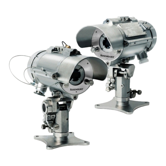
Toxic open path gas detector
Hide thumbs
Also See for Rosemount 936:
- Reference manual (76 pages) ,
- Reference manual (26 pages) ,
- Reference manual (64 pages)

Related Manuals for Emerson Rosemount 936


Summary of Contents for Emerson Rosemount 936
- Page 1 Quick Start Guide 00825-0100-4036, Rev AA April 2021 ™ Rosemount Toxic Open Path Gas Detector...
- Page 2 Emerson. While great efforts have been made to ensure the accuracy and clarity of this document, Emerson assumes no responsibility resulting from any omissions in this document or from misuse of the information obtained herein.
-
Page 3: Table Of Contents
April 2021 Quick Start Guide Abbreviation Meaning Immune at any distance IECEx International Electrochemical Commission explosion Internet protocol Refers to the three infrared sensors Light-emitting diode Liquified natural gas MilliAmps (0.001 amps) ® Modbus Master-slave messaging structure Not applicable National pipe thread NTSC National Television System Committee (a color encoding system) Phase alternation by line (a color encoding system) - Page 4 Quick Start Guide April 2021 Emerson.com/Rosemount...
-
Page 5: Installation
April 2021 Quick Start Guide Installation General considerations 1.1.1 Personnel Only employ suitably qualified personnel who are familiar with the local codes and practices and trained for gas detection maintenance. Ensure that wiring is only performed and supervised by someone with knowledge of electronics and, in particular, wiring installation. - Page 6 April 2021 1.1.3 Site requirements When installing the Rosemount 936, take into account the weight of the monitored gas compared to that of the surrounding air and the individual site requirements. Ensure that the site selected gives the detector a direct view to the source.
- Page 7 April 2021 Quick Start Guide separation distance between the neighboring OPGD systems according to the installation lengths as listed in Table 1-2. Table 1-2: Minimum Separation Distances Installation line of sight distance, ft. Minimum separation, ft. (m) 33 (10) 3.3 (1) 66 (20) 5 (1.5) 98 (30)
- Page 8 • Handle for cover opening • Alignment tool kit • Function check filter: for H S or NH Other accessories are available, per customer request: • Pole mount (u-bolt 5 in. [127 mm]) ® • HART handheld harness kit Emerson.com/Rosemount...
- Page 9 April 2021 Quick Start Guide • Protective cover 1.2.2 Required tools You can install the detector using general purpose common tools and equipment. Table 1-3: Tools Tool Function Alignment kit Provides tools to install fine alignment tool. Hex key 8 mm Mounts the detector on the tilt mount.
- Page 10 0 µF 0 µF 0 µF 0 µF 0 µF 0 µF 0 µH 0 µH 0 µH 0 µH 0 µH 0 µH 0 µH 22 µF 22 µF 22 µF 22 µF 22 µF 22 µF 22 µF Emerson.com/Rosemount...
- Page 11 April 2021 Quick Start Guide Paramet Channels ® Light- LED 2 HART RS485+ RS485- emitting connecti combine diode (LED) 1 7.5 mH 7.5 mH 7.5 mH 7.5 mH 7.5 mH 514 µH 96.9 µH Note Co @ 6.6 V is 22 µF, as per Table A.2 of IEC 60079-11:2011. Lo is calculated based on 1.5 times current for IIC, 40 µJ using E = 0.5 *(LI) 1.3.2 Special conditions for safe use from ATEX IECEx certificate...
- Page 12 • Where Um does not exceed 50 Vac or 120 Vdc, in a SELV or PELV system or • Via a safety isolating transformer complying with the requirements of CAN/CSA-C22.2 No. 66.1 or technically equivalent standard or Emerson.com/Rosemount...
- Page 13 April 2021 Quick Start Guide • Directly connected to apparatus complying with CAN/CSA-C22.2 No. 60950-1, CAN/CSA-C22.2 No. 61010-1 or technically equivalent standard or • Fed directly from cells or batteries. 4. The output of the optical radiation source with respect to explosion protection meets Exception 3 from the scope of CAN/CSA-C22.2 No.
- Page 14 8. The equipment shall be supplied with Class 2 as defined in article 725.121 or NFPA 70. Install conduits and cables The conduit and cable installation must comply with the following guidelines: • To avoid water condensation in the detector, install it with the conduits/ cable entries facing downwards. Emerson.com/Rosemount...
- Page 15 April 2021 Quick Start Guide • Use flexible conduits/cables for the last portion connecting to the detector. • When pulling the cables through the conduits, ensure that they are not tangled or stressed. Extend the cables about 12-in. (30 cm) beyond the detector location to accommodate wiring after installation.
- Page 16 Quick Start Guide April 2021 Figure 1-2: Mounting the Tilt Mount and Detector A. Front shield B. Back cover C. Security screw D. Locating pins E. Alternate mounting location Emerson.com/Rosemount...
- Page 17 April 2021 Quick Start Guide Figure 1-3: Tilt Mount A. Detector/source holding plate B. Vertical fine alignment screw C. Tilt mount holding plate D. Horizontal fine alignment screw E. Vertical crude alignment tightening screw F. Vertical fine alignment tightening screw G.
- Page 18 Prior to mounting the tilt mount to a stable surface, verify that the line of site is unobstructed and corresponds to the detector's installation distance. Procedure 1. Place the tilt mount holding plate in its designated location and secure it with four fasteners through four holes with diameters of 0.3-in. (8.5 mm). Emerson.com/Rosemount...
- Page 19 April 2021 Quick Start Guide NOTICE Skip this step if the tilt mount is already installed. Removing the detector for maintenance purposes does not require removing the tilt mount. 2. Place the detector with its conduit/cable inlets pointing downwards on the detector holding plate of the tilt mount. 3.
- Page 20 2. Remove the protective plug mounted on the detector conduit/cable entry inlet. 3. Pull the wires through the detector inlet conduit. 4. Use a ¾-in. - 14 national pipe thread (NPT) or M25 x 1.5 conduit connection/cable gland to assemble the cable conduit to the detector. Emerson.com/Rosemount...
- Page 21 April 2021 Quick Start Guide 5. Connect the wires to the required terminals according to the wiring diagram. Wiring to detector terminals Wiring configurations. 6. Connect the grounding wire to the ground screw outside the detector. The detector must be well grounded to earth ground. 7.
- Page 22 3. Connect the wires to the required terminals according to the wiring diagram. Wiring to source terminals. 4. Connect the grounding wire to the ground screw located on the exterior of the detector. Ensure that the source is well grounded to earth ground. Emerson.com/Rosemount...
- Page 23 April 2021 Quick Start Guide Note In case of installation in the US, use the internal grounding connection for the equipment grounding connection and the external connection for a supplementary bonding connection where local codes or authorities permit or require such connection. The external bonding conductor is manufactured from copper and is 4 in size.
- Page 24 5. Approximately aim the source vertically towards the detector. 6. Tighten the outer vertical lock screw. 7. Repeat this process for the detector. 1.9.2 Perform fine alignment Refer to Figure 1-4 to see the detector with the alignment tool installed. Emerson.com/Rosemount...
- Page 25 April 2021 Quick Start Guide Procedure 1. Remove the front shield and mount the alignment tool on the front of the source using the three screws. The alignment tool is supplied in the commissioning kit. 2. Aim the source towards the detector within the horizontal access. 3.
-
Page 26: Operation
2. Ensure that the 4-20 mA wiring meter is connected to the detector. 3. Power up the system 18 to 32 Vdc. After sixty seconds, the current meter indicates 4 mA. Postrequisites After powering up, zero calibrate the system. See Zero calibrate. Emerson.com/Rosemount... - Page 27 April 2021 Quick Start Guide Verify signal Use a Field Communicator to verify the signal. Figure 2-1: Light-Emitting Diode (LED) Indication Before Zero Calibration 1. Verify LED indication. ® 2. Use Winhost or HART to verify installation parameters. 2.3.1 Signal limits Table 2-1: Maintenance Channels' Limits Channel Short range...
- Page 28 D. Maximum range E. Reference minimum F. Signal minimum G. Ratio H. NQ ratio Zero calibrate Prerequisites Zero calibrate after any of the following: • Installation • Realignment • Window cleaning • Any change in detector or source position Emerson.com/Rosemount...
- Page 29 April 2021 Quick Start Guide WARNING Only zero calibrate when: No combustible gases are present. There is a clear path between the source and the detector. Weather conditions are clear. Before zero calibrating, align the detector precisely. Figure 2-3: Calibrating with a Hand-Held Communicator Quick Start Guide...
- Page 30 Quick Start Guide April 2021 ® Figure 2-4: Screens shown when Calibrating with WinHost Software Emerson.com/Rosemount...
- Page 31 April 2021 Quick Start Guide Figure 2-5: Magnetic Mode Selector A. Magnet To switch from each position (Step 1 through Step 3), use either Winhost, ® HART , or RS-485 or move the magnetic mode selector above the magnetic switch (see Figure 2-5).
- Page 32 2. Check that the detector reading is within the range specified in the factory acceptance test (FAT) certificate. 3. Remove all filters and wait 30 to 60 seconds. Then verify that the detector returns to Normal status (light-emitting diode [LED] is green and blinking, and the output is 4 mA). Emerson.com/Rosemount...
-
Page 33: Product Certifications
The alert condition according to SIL-2 can be implemented by alert signal via 0-20 mA current loop. TR CU The Rosemount 936 is in compliance with the standard TR CU 012/2011 per: 1Ex db eb ib [ib Gb] IIB + H2 T4 Gb X Ex tb IIIC T135 °C Db X -55 °C ≤... - Page 34 Class I Zone 1 AEx db eb ib [ib Gb] IIB+H T4 Gb Zone 21 AEx tb [ib Db] IIIC T135 °C Db = -55 °C to +65 °C The Rosemount 936 is a "Class 1 Laser Product" per IEC 60825-1: 2014 ed. Emerson.com/Rosemount...
-
Page 35: Wiring Configurations
April 2021 Quick Start Guide Wiring configurations Figure A-1: Detector Wiring Terminal A. Power (+) 18 to 32 Vdc B. Return (-) C. 0-20 mA (input) D. 0-20 mA (output) E. RS-485 (+) F. RS-485 (-) G. Ground Quick Start Guide... - Page 36 Quick Start Guide April 2021 Figure A-2: Source Wiring Terminal A. Power (+) 18 to 32 Vdc B. Return (-) C. Not used D. RS-485 (+) E. RS-485 (-) F. Ground Emerson.com/Rosemount...
- Page 37 April 2021 Quick Start Guide Figure A-3: 0-20 mA Sink 4 Wire A. Detector B. Controller C. Input power: 18-32 Vdc D. Return E. 0-20 mA meter Quick Start Guide...
- Page 38 Figure A-4: 0-20 mA Non-Isolated Sink 3 Wire A. Detector B. Controller C. Input power: 18-32 Vdc D. Return E. 0-20 mA meter Figure A-5: 0-20 mA Source 3 Wire A. Detector B. Controller C. Input power: 18-32 Vdc D. Return E. 0-20 mA meter Emerson.com/Rosemount...
- Page 39 Quick Start Guide RS-485 communication network Using the RS-485 network capability of the Rosemount 936 detector and additional software, it is possible to connect up to 32 detectors in an addressable system with four wires only (two for power and two for communication).
- Page 40 Quick Start Guide April 2021 Emerson.com/Rosemount...
-
Page 41: Declaration Of Conformity
April 2021 Quick Start Guide Declaration of Conformity Quick Start Guide... - Page 42 Quick Start Guide April 2021 Emerson.com/Rosemount...
- Page 43 April 2021 Quick Start Guide Quick Start Guide...
- Page 44 For more information: www.emerson.com © 2021 Emerson. All rights reserved. Emerson Terms and Conditions of Sale are available upon request. The Emerson logo is a trademark and service mark of Emerson Electric Co. Rosemount is a mark of one of the Emerson family of companies.
Need help?
Do you have a question about the Rosemount 936 and is the answer not in the manual?
Questions and answers