Emerson Rosemount 936 Reference Manual
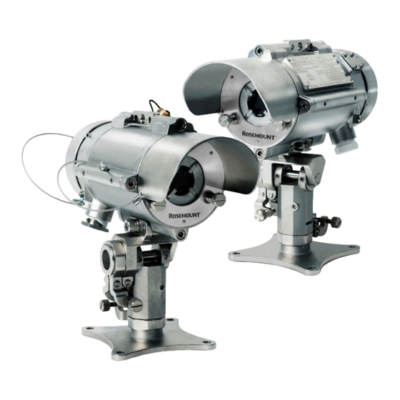
Open path toxic gas detectors
Hide thumbs
Also See for Rosemount 936:
- Reference manual (76 pages) ,
- Quick start manual (44 pages) ,
- Reference manual (26 pages)

Related Manuals for Emerson Rosemount 936


Summary of Contents for Emerson Rosemount 936
- Page 1 Reference Manual 00809-0100-4036, Rev AF May 2023 Rosemount ™ Open Path Toxic Gas Detectors...
- Page 2 Emerson does not assume any liability arising out of the application or any use of any product or circuit described herein; neither does it convey license under its patent rights or the rights of others.
-
Page 3: Table Of Contents
6.5 Conduit/cable installation......................32 6.6 Receiver/transmitter mounting....................32 6.7 Receiver wiring.......................... 33 6.8 Receiver terminal wiring......................36 6.9 Transmitter wiring........................37 Chapter 7 Operating instructions......................39 7.1 Safety operation........................39 7.2 Alignment of unit........................39 7.3 Powering up the system......................40 7.4 Safety precautions........................40 7.5 Signal verification........................41 7.6 Zero calibration..........................41 7.7 Functional check........................42 Rosemount 936... - Page 4 C.6 HART handled diagnostic unit....................57 C.7 Universal RS-485 and HART IS harness kit................57 C.8 USB/RS-485 harness converter kit..................58 C.9 Protective cover.........................58 Appendix D SIL-2 features...........................59 D.1 Safety relevant parameters..................... 59 D.2 General conditions for safe use....................59 Appendix E Configuring the short range model..................61 Emerson.com/Rosemount...
-
Page 5: About This Guide
May 2023 1 About this guide This guide describes the Rosemount 936 Gas Detector and its features and provides instructions how to install, operate, and maintain the receiver. Note This user guide should be carefully read by all individuals who have or will have responsibility for using, maintaining or servicing the product. -
Page 6: Notifications
This indicates a potentially hazardous situation that could result in serious injury and/or major damage to the equipment. CAUTION This indicates a situation that could result in minor injury and/or damage to the equipment. Note This provides supplementary information, emphasizes a point or procedure, or gives a tip to facilitate operation. Emerson.com/Rosemount... -
Page 7: Chapter 2 Product Overview
May 2023 2 Product overview The Rosemount 936 Gas Detector employs an advanced Xenon UV Transmitter and integrated electronics package, both of which are encased in improved stainless steel housings, which provide high quality and performance, fast response, and line-of-sight gas monitoring. - Page 8 Product overview Reference Manual May 2023 00809-0100-4036 Emerson.com/Rosemount...
-
Page 9: Chapter 3 Technical Description
Approved to Safety Integrity Level 2 (SIL2 - TÜV) • High reliability - MTBF-minimum 100,000 hours 3.2 Applications The Rosemount 936 Gas Detector system can be used to monitor toxic gas concentration in various applications, such as: • Petrochemical, pharmaceutical, and other chemical storage and production areas •... - Page 10 S has a characteristically strong absorption in the solar blind range of 189–270 nm, which enables its fast and reliable detection at low concentrations. • Sulphur dioxide (SO ): A colorless gas with a strong odor which is produced when a material, or fuel, containing sulphur is burned. Emerson.com/Rosemount...
- Page 11 The Xenon UV Source was introduced in the initial detector development, and was designed to overcome false alarms, which were experienced by early generations of the open path system. The new Rosemount 936 detector employs the latest generation of UV bulbs to provide even more power, and an extended operation life.
-
Page 12: Product Certification
–55 °C to +65 °C Ambient 3.4.3 SIL-2 The Rosemount 936 is TUV approved for SIL-2 requirements per IEC 61508. According to SIL-2 requirements, the alert condition can be implemented by an alert signal via the 0–20 mA current loop. 3.4.4 ... -
Page 13: Model And Types
Zone 21 AEx tb [ib Db] IIIC T135 °C Db = -55 °C to +65 °C = -55 °C to +65 °C The Rosemount 936 is a "Class 1 Laser Product" per IEC 60825-1: 2014 ed. 05. 3.4.7 Performance approvals ANSI/ISA-92.00.04-2014... -
Page 14: Description
• UV source (transmitter) • Infrared detector (receiver) The Rosemount 936 detects gases over an open path transmitted from the UV transmitter to the receiver. 3.6.1 UV transmitter unit The UV transmitter unit emits UV radiation pulses at the rate of 1 pulse per second. The pulse width (5–10μsec) is very powerful. - Page 15 The front window of the receiver is heated to improve performance in ice, condensation, and snow conditions. There is one detector type that is suitable for the H S / SO version and one for the NH version. Rosemount 936...
- Page 16 Figure 3-2: Detector A. Front window section B. Label C. Main housing D. Mounting plate E. Intrinsically safe connector (RS-485/HART ® F. Back cover G. Earth terminal H. Front window I. Inlet conduit J. Inlet conduit K. Indicator LED Emerson.com/Rosemount...
-
Page 17: Chapter 4 Operating Modes
• Low voltage fault (1 mA output) Detection is disabled due to a low voltage supply. The receiver returns to proper operation when the correct voltage level is restored. • Fault 2 (1 mA output) Rosemount 936... -
Page 18: Visual Indicators
Table 4-2: Receiver LED indications Receiver status LED color LED mode Fault Amber 4 Hz – flashing Normal Green 1 Hz – flashing 4.3 Output signals The system provides the following outputs: • 0–20 mA current output • RS-485 interface Emerson.com/Rosemount... -
Page 19: System Setup
PC. 4.4 System setup 4.4.1 Field configuration The Rosemount 936 incorporates several functions that can be set by the customer, using: • Host software: For additional settings and trouble shooting, use the software on the product web page. •... - Page 20 PC software host or a handheld unit. The standard setup is as follows: Table 4-4: Receiver default setup Function Setup 0–20 mA Continuous Heat mode Auto Heat on Emerson.com/Rosemount...
-
Page 21: Technical Specifications
Does not produce a false alarm and is not influenced by Immunity to false alarm: • Solar radiation • Hydrocarbon flames • Other external IR or UV radiation sources • Rain conditions or water spray Per the requirements listed in the following performance standards: • EN 60079-29-4 Rosemount 936... -
Page 22: Electrical Specifications
Modbus devices to the same network. 5.3.3 HART protocol ® The HART protocol is a digital communication signal at low levels in addition to the 0–20 This bi-directional field communication protocol is used to communicate between intelligent field instruments and the host system. Emerson.com/Rosemount... -
Page 23: Mechanical Specifications
Tilt mount 4.2 lb 1.9 kg 5.5 Environmental specifications The Rosemount 936 system is designed to withstand harsh environmental conditions. The transmitter and receiver units compensate for adverse conditions while maintaining accuracy. 5.5.1 High temperature The system conforms to DNVGL-CG-0339, class D. - Page 24 To fully comply with EMC directive 2014/30/EU and protect against interference caused by RFI and EMI, the cable to the receiver must be shielded and the receiver must be grounded. The shield should be grounded at the receiver end. Emerson.com/Rosemount...
-
Page 25: Chapter 6 Installation Instructions
The mounting point for each item should be secure and stable with minimal vibrations • Equipment should be either mounted in a position where it cannot be knocked out of alignment, or it is guarded from physical impact, above human height to avoid partial obscuration. Rosemount 936... - Page 26 The selected wire gauge should be based on the number of receivers used on the same loop, and the distance from the control unit. The maximum number of wire connections in a terminal is 2 wire cross-sections, each of 1 mm Emerson.com/Rosemount...
-
Page 27: Preparations For Installation
2. Record the part number (P/N) and serial number of the receivers and transmitter units, and the installation date in an appropriate logbook. 3. Open the container package immediately, prior to installation, and visually inspect the receivers, transmitters, and accessories. Rosemount 936... -
Page 28: Certification Instructions
The output of the optical radiation source with respect to explosion protection meets Exception 3 from the scope of UL 60079-28. • Special conditions for safe use: The Rosemount 936 Receiver and UV Transmitter Units should not be used as safety related devices, in accordance with directive 2014/34/EU. Emerson.com/Rosemount... - Page 29 Via a safety isolating transformer, complying with the requirements of IEC 61588-2-6 or technically equivalent standard — Directly connected to apparatus, complying with IEC 60950, IEC 61010-1, or technically equivalent standard — Fed directly from cells or batteries Rosemount 936...
- Page 30 6. Equipment has only been tested for electrical safety. No evaluation of functional safety and performance characteristics has been conducted. 7. The equipment shall be supplied with Limited Energy Circuit (LEC) as defined in CSA C22.2 No. 61010-1-12 or Limited Power Source (LPS) as defined in CAN/CSA C22.2 No. 60950-1. Emerson.com/Rosemount...
- Page 31 6. Equipment is only to be installed by manufacturer trained personnel. 7. Equipment has only been tested for electrical safety. No evaluation of functional safety and performance characteristics has been conducted. 8. The equipment shall be supplied with Class 2 as defined in article 725.121 of NFPA Rosemount 936...
-
Page 32: Conduit/Cable Installation
(B). Secure the receiver with M10 x 1.5 screws with No. M10 spring washers (I, J). Secure the receiver to the tilt mount using Hex Key No. 7 for M10 x 1.5 screws (I). 3. Repeat Step 1 Step 2 for installing the transmitter. Emerson.com/Rosemount... -
Page 33: Receiver Wiring
. A tightening torque of 16 in-lb (1.8 N-m) shall be used to secure the bonding conductor. 5. Place and secure the receiver’s back cover by screwing on the cover and securing it using the secure bolt (Figure 6-2, Item O). Rosemount 936... - Page 34 B. Transmitter or receiver holding plate C. Vertical crude alignment tightening screw D. Vertical fine alignment tightening screw E. Horizontal fine alignment tightening screw F. Horizontal crude alignment tightening screw G. Horizontal fine alignment screw H. Vertical fine alignment screw Emerson.com/Rosemount...
- Page 35 G. Vertical fine alignment screw H. Horizontal fine alignment screw I. Receiver tightening screw J. Receiver tightening washer K. Receiver L. Alignment tool M. Alignment tool tightening bolt N. Receiver back cover O. Receiver back cover secure bolt Rosemount 936...
-
Page 36: Receiver Terminal Wiring
The receiver has six wiring terminals. The following table lists the functions of each electrical terminal of the receiver. Table 6-4: Wiring options Terminal number Function Power +24 VDC Return –24 VDC 0–20 mA In (+) 0–20 mA Out (–) RS-485 (+) RS-485 (–) Emerson.com/Rosemount... -
Page 37: Transmitter Wiring
5. Place and secure the transmitter unit’s back cover by screwing on the cover and securing the back screw bolt. 6.9.2 Terminal wiring The contains six wiring terminals. Table 6-5: wiring options Terminal number Function Power +24 VDC Return –24 VDC Spare Spare Spare Spare Rosemount 936... - Page 38 Installation instructions Reference Manual May 2023 00809-0100-4036 Figure 6-4: Transmitter with cover removed A. Housing B. Terminal board C. Earth terminal D. Inlet conduit E. Internal earth connection F. Transmitter holding plate Emerson.com/Rosemount...
-
Page 39: Chapter 7 Operating Instructions
Use a ¼-in. Allen screwdriver for all alignment screws. b. Loosen screws E and F. c. Approximately aim the transmitter horizontally toward the receiver. d. Tighten screw F. e. Loosen screws C and D. f. Approximately aim the transmitter vertically toward the receiver. Rosemount 936... -
Page 40: Powering Up The System
Follow the manual instructions, and refer to the drawings and specifications issued by the manufacturer. • Do not open the transmitter or receiver housing while power is connected. • External devices such as automatic extinguishing systems must be disconnected before performing maintenance tasks required by the warranty. Emerson.com/Rosemount... -
Page 41: Signal Verification
To perform the zero calibration procedure: To perform the zero calibration procedure use the HART software (refer to the product web page), or Modbus software on the RS-485 interface (refer to the product web page). Rosemount 936... -
Page 42: Functional Check
This difference is the 0–20 mA current variance. 5. Record the 0–20 mA current variance in the maintenance logbook. If the variance is more than a 30% change when compared to the previous check (see delivery form), repeat the alignment. Emerson.com/Rosemount... -
Page 43: Chapter 8 Maintenance Instructions
6. Enter the date, name of company, and person who performed the maintenance service into the maintenance logbook. 7. Reconnect the power to the transmitter and receiver. 8. Perform signal verification (see Signal verification). 9. Perform zero calibration (see Zero calibration). 10. Perform a functional check (see Functional check). Rosemount 936... - Page 44 8.2.3 Functional check of unit The Rosemount 936 has been calibrated at the factory according to the user’s specific gas or vapor detection requirements. Use the check filters included in the commissioning kit according to the corresponding calibrating gas to validate correct installation. Refer to Functional check for instructions.
-
Page 45: Chapter 9 Troubleshooting
Ratio 1 and Ratio 2 out of the Poor alignment Perform alignment limit Dirt on the window Clean the window Receiver fault Replace/repair receiver Voltage less than 16 VDC. The Low input voltage Check the power supply and Receiver at “V” fault. installation Rosemount 936... - Page 46 Troubleshooting Reference Manual May 2023 00809-0100-4036 Emerson.com/Rosemount...
-
Page 47: Declaration Of Conformity
Reference Manual Declaration of Conformity 00809-0100-4036 May 2023 10 Declaration of Conformity Rosemount 936... - Page 48 Declaration of Conformity Reference Manual May 2023 00809-0100-4036 Emerson.com/Rosemount...
-
Page 49: Appendix A Ordering Information
Reference Manual Ordering information 00809-0100-4036 May 2023 A Ordering information You can order the Rosemount 936 as separate parts: source (PN 936TXT00XXXX), detector (PN 936RT12XXXXX), and accessories. • Accurate and reliable high-speed response in under three seconds • Utilizes ultraviolet technology •... -
Page 50: Detector (Receiver)
Product certifications Code Description ATEX, IECEx, UKCA CSA C/US InMetro (pending) TR CU (EAC) (pending) Republic of Korea A.5 Detector (Receiver) A.5.1 Required model components Model Code Description Toxic Open Path Gas Detector (Receiver) Receiver selection Code Description Receiver Emerson.com/Rosemount... - Page 51 Code Description Hydrogen sulfide (receiver) Ammonia (receiver) Housing style / conduit Code Material Measurement Stainless steel ¾-in. NPT Stainless steel Product certifications Code Description ATEX, IECEx, UKCA CSA C/US InMetro (pending) TR CU (EAC) (pending) Republic of Korea Rosemount 936...
- Page 52 Ordering information Reference Manual May 2023 00809-0100-4036 Emerson.com/Rosemount...
-
Page 53: Appendix B Wiring Configurations
Reference Manual Wiring configurations 00809-0100-4036 May 2023 B Wiring configurations Figure B-1: Receiver wiring terminal Figure B-2: Transmitter wiring terminal Rosemount 936... -
Page 54: Rs-485 Communication Network
B.1 RS-485 communication network By using the RS-485 network capability of the Rosemount 936 Receiver and additional software, it is possible to connect up to 32 receivers in an addressable system with four wires only (two for power and two for communication). Using repeaters, the number of receivers can be much larger (32 receivers for each repeater): up to 247 on the same four wires. - Page 55 Reference Manual Wiring configurations 00809-0100-4036 May 2023 Figure B-6: RS-485 networking for wiring option 3 A. Controller B. First receiver C. Last receiver D. Power supply E. RS-485 computer port Rosemount 936...
- Page 56 Wiring configurations Reference Manual May 2023 00809-0100-4036 Emerson.com/Rosemount...
-
Page 57: Appendix C Accessories
C.7 Universal RS-485 and HART IS harness kit It includes a quick plug connection for a HART handheld unit and an RS-485 interface. The HART unit can be loaded with Rosemount host software. The RS-485 interface is for Rosemount 936... -
Page 58: Usb/Rs-485 Harness Converter Kit
The USB RS-485 Harness Kit with RS-485/USB converter (P/N 794079), together with Modbus Manager host software, enables the user to connect to any available PC or laptop to reconfigure settings or perform diagnostics on the Rosemount 936 gas detection system. -
Page 59: Appendix Dsil-2 Features
The alarm conditions of the transmitter must be checked periodically together with standard gas calibration checks. The Open-Path Gas must be switched off and on. • The connected controller must monitor the 0–20 mA signal current for values below 4 mA and above 20 mA. Rosemount 936... - Page 60 SIL-2 features Reference Manual May 2023 00809-0100-4036 • Mean time to repair should be 72 hours. Emerson.com/Rosemount...
-
Page 61: Appendix E Configuring The Short Range Model
Configuring the short range model The short range model detects hydrogen sulfide (H S) gas at a distance of 17 – 52 ft. (5 – 16 Table E-1: Rosemount 936 H S Open Path Gas Detector Series Range Source (transmitter) - Page 62 Configuring the short range model Reference Manual May 2023 00809-0100-4036 Figure E-1: Using RS-485 and Winhost Figure E-2: Using HART DD Emerson.com/Rosemount...
- Page 63 Reference Manual 00809-0100-4036 May 2023 Rosemount 936...
- Page 64 Emerson Terms and Conditions of Sale are available upon request. The Emerson logo is a trademark and service mark of Emerson Electric Co. Rosemount is a mark of one of the Emerson family of companies. All other marks are the property of their respective owners.
Need help?
Do you have a question about the Rosemount 936 and is the answer not in the manual?
Questions and answers