
Related Manuals for Kramer VP-451


Summary of Contents for Kramer VP-451
- Page 1 USER MANUAL MODEL: VP-451 HDMI / USB-C Scaler P/N: 2900-301231 Rev 1 www.kramerAV.com...
-
Page 2: Table Of Contents
Kramer Electronics Ltd. Contents Introduction Getting Started Overview Typical Applications Defining VP-451 HDMI / USB-C Scaler Mounting VP-451 Connecting VP-451 Connecting the Output to a Balanced/Unbalanced Stereo Audio Acceptor Connecting the Remote Control Switches Operating and Controlling VP-451 Using Front Panel Buttons... -
Page 3: Introduction
Kramer Electronics Ltd. Introduction Welcome to Kramer Electronics! Since 1981, Kramer Electronics has been providing a world of unique, creative, and affordable solutions to the vast range of problems that confront the video, audio, presentation, and broadcasting professional on a daily basis. In recent years, we... -
Page 4: Overview
European Advanced Recycling Network (EARN) and will cover any costs of treatment, recycling and recovery of waste Kramer Electronics branded equipment on arrival at the EARN facility. For details of Kramer’s recycling arrangements in your particular country go to our recycling pages at www.kramerav.com/support/recycling. -
Page 5: Typical Applications
• Meeting rooms and huddle spaces. • Conversion between video formats. • Charging USB-C devices. Controlling your VP-451 Control your VP-451 via the front panel buttons and via contact closure switches. VP-451 – Introduction... -
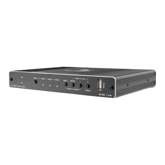
Page 6: Defining Vp-451 Hdmi / Usb-C Scaler
Kramer Electronics Ltd. Defining VP-451 HDMI / USB-C Scaler This section defines VP-451. Figure 1: VP-451 HDMI / USB-C Scaler Front Panel Feature Function ON LED Lights green when the unit is powered. INPUT Button Press to cycle the input between USB-C, HDMI 1 and HDMI 2. - Page 7 Kramer Electronics Ltd. Figure 2: VP-451 HDMI / USB-C Scaler Rear Panel Feature Function AUDIO IN 3.5mm Mini Jack Connect to an unbalanced stereo audio PC source. Can also be selected as the audio input (instead of the HDMI and USB-C embedded audio inputs).
-
Page 8: Mounting Vp-451
Kramer Electronics Ltd. Mounting VP-451 This section provides instructions for mounting VP-451. Before installing, verify that the environment is within the recommended range: • Operation temperature – 0 to 40C (32 to 104F). • Storage temperature – -40 to +70C (-40 to +158F). -
Page 9: Connecting Vp-451
Kramer Electronics Ltd. Connecting VP-451 Always switch off the power to each device before connecting it to your VP-451. After connecting your VP-451, connect its power and then switch on the power to each device. Figure 3: Connecting to the... -
Page 10: Connecting The Output To A Balanced/Unbalanced Stereo Audio Acceptor
Connecting the Remote Control Switches Momentarily connect the desired pin to the GND pin to select an input: Pin Name Function USB-C Select the USB-C input. HDMI 1 Select the HDMI 1 input. HDMI 2 Select the HDMI 2 input. VP-451 – Connecting VP-451... -
Page 11: Operating And Controlling Vp-451
Setting Switching Mode on page 13. • Setting FREEZE Mode Functionality on page 13. • Managing EDID on page 14. • Viewing Device Information on page 14. • Performing Factory Reset on page 15. VP-451 – Operating and Controlling VP-451... - Page 12 Selecting an Input Signal To set the input source: 1. On the front panel press MENU. The menu appears. 2. Click INPUT and select the SOURCE: ▪ HDMI 1(default). ▪ HDMI 2. ▪ Type C. VP-451 – Operating and Controlling VP-451...
- Page 13 Set each input audio source to AUTOMATIC (default, the embedded audio is used unless a DVI source is detected), or LINE IN (analog is used). OUTPUT VOLUME Set the AUDIO OUT output volume (default is 80 = 0dB). VP-451 – Operating and Controlling VP-451...
- Page 14 To set Auto Sync Off: 1. On the front panel press MENU. The menu appears. 2. Click ADVANCED and select Auto Sync Off. 3. Define Auto Sync Off according to the information in the following table: VP-451 – Operating and Controlling VP-451...
- Page 15 3. Set a panel lock mode according to the information in the following table: Menu Item Function FREEZE + MUTE (default) Freeze and mute the display. ONLY FREEZE Freeze the display. ONLY MUTE Mute the output audio. VP-451 – Operating and Controlling VP-451...
- Page 16 Device information includes the selected source, the input and output resolutions, and the software version. To view the information: 1. On the front panel press MENU. The menu appears. 2. Click INFO and view the input resolution, output resolution and software version. VP-451 – Operating and Controlling VP-451...
- Page 17 To perform factory reset: 1. On the front panel press MENU. The menu appears. 2. Click FACTORY and select Reset 3. Click Yes. Wait for completion of factory reset (resolution is set to Native). VP-451 – Operating and Controlling VP-451...
-
Page 18: Upgrading The Firmware
During upgrade the LEDs flash and once complete, one of the INPUT LEDs turns on and a valid signal appears on the output. 6. Check that the OSD Info screen shows the latest FW version. VP-451 – Upgrading the Firmware... -
Page 19: Technical Specifications
0.7kg (1.5lbs) approx. Shipping Weight 1.3kg (2.9lbs) approx. Accessories Included Power cord and adapter Optional For optimum range and performance use the recommended Kramer cables available at www.kramerav.com/product/VP-451 Specifications are subject to change without notice at www.kramerav.com VP-451 – Technical Specifications... -
Page 20: Input Resolutions
2048x1080 50/60Hz 1280x800 60Hz 2560x1440 RB 60Hz 1280x1024 60Hz 720x480P 60Hz 1360x768 60Hz 720x576P 50Hz 1400x1050 60Hz 1280x720P 50/60Hz 1440x900 60Hz 1920x1080P 24/25/30/50/60Hz 1600x1200 60Hz 2560x1080P 50/60Hz 1680x1050 60Hz 4K2K 24/25/30/50/60Hz 1920x1200 RB 60Hz 4K2K (4:2:0) 50/60Hz VP-451 – Technical Specifications... -
Page 21: Default Edid
Modeline...."1920x1200" 154.000 1920 1968 2000 2080 1200 1203 1209 1235 +hsync -vsync CE video identifiers (VICs) - timing/formats supported 1920 x 1080p at 60Hz - HDTV (16:9, 1:1) 1920 x 1080p at 50Hz - HDTV (16:9, 1:1) 1280 x 720p at 60Hz - HDTV (16:9, 1:1) VP-451 – Technical Specifications... - Page 22 Maximum TMDS clock..35MHz Reserved video related data Data payload..... 0F000003 Report information Date generated... 3/24/2020 Software revision..2.70.0.989 Data source....Real-time 0x0041 Operating system..6.1.7601.2.Service Pack 1 Raw data 00,FF,FF,FF,FF,FF,FF,00,2D,B2,0D,06,31,00,00,00,06,1C,01,03,80,24,24,8C,C2,90,20,9C,54,50,8F,26, 21,52,56,2F,CF,00,A9,40,81,80,90,40,D1,C0,31,59,45,59,61,59,81,99,08,E8,00,30,F2,70,5A,80,B0,58, 8A,00,BA,88,21,00,00,1E,02,3A,80,18,71,38,2D,40,58,2C,45,00,BA,88,21,00,00,1E,00,00,00,FC,00,56, 50,2D,34,35,31,0A,20,20,20,20,20,20,00,00,00,FD,00,17,3D,0F,88,3C,00,0A,20,20,20,20,20,20,01,2F, 02,03,3B,F0,52,10,1F,04,13,05,14,02,11,06,15,22,21,20,5D,5E,5F,60,61,23,09,07,07,83,01,00,00,6E, 03,0C,00,10,00,78,3C,20,00,80,01,02,03,04,67,D8,5D,C4,01,78,80,07,E4,0F,00,00,03,9A,29,A0,D0,51, 84,22,30,50,98,36,00,10,0A,00,00,00,1C,66,21,56,AA,51,00,1E,30,46,8F,33,00,10,09,00,00,00,1E,28, 3C,80,A0,70,B0,23,40,30,20,36,00,10,0A,00,00,00,1A,00,00,00,00,00,00,00,00,00,00,00,00,00,00,E0 VP-451 – Technical Specifications...
- Page 23 Electronics products, this product must be insured during shipment, with the insurance and shipping charges prepaid by you. I f this product is returned uninsured, you assume all risks of loss or damage during shipment. Kramer Electronics will not be responsible for any costs related to the removal or re - installation of this product from or into any installation.
- Page 24 SAFETY WARNING Disconnect the unit from the power supply before opening and servicing For the latest information on our products and a list of Kramer distributors, visit our Web site where updates to this user manual may be found. We welcome your questions, comments, and feedback.
Need help?
Do you have a question about the VP-451 and is the answer not in the manual?
Questions and answers