
Related Manuals for Kramer VP-434


Summary of Contents for Kramer VP-434
-
Page 1: User Manual
K R A ME R E LE CT R O N IC S L T D . USER MANUAL MODEL: VP-434 Component UXGA HDMI Scaler P/N: 2900-000346 Rev 6... -
Page 3: Table Of Contents
Using the Infrared Remote Control Transmitter Technical Specifications Figures F igure 1: VP-434 Component/UXGA HDMI Scaler F igure 2: Connecting the VP-434 Component/UXGA HDMI Scaler F igure 3: Connecting the Contact Closure Remote Control PINs F igure 4: Infrared Remote Control Transmitter VP-434 – Contents... -
Page 4: Introduction
Introduction Welcome to Kramer Electronics! Since 1981, Kramer Electronics has been providing a world of unique, creative, and affordable solutions to the vast range of problems that confront video, audio, presentation, and broadcasting professionals on a daily basis. In recent years, we have redesigned and upgraded most of our... -
Page 5: Getting Started
Avoid interference from neighboring electrical appliances that may adversely influence signal quality • Position your Kramer VP-434 away from moisture, excessive sunlight and dust This equipment is to be used only inside a building. It may only be connected to other equipment that is installed inside a building. -
Page 6: Safety Instructions
Kramer Electronics has made arrangements with the European Advanced Recycling Network (EARN) and will cover any costs of treatment, recycling and recovery of waste Kramer Electronics branded equipment on arrival at the EARN facility. For details of Kramer’s recycling arrangements in your particular country go to our recycling pages at http://www.kramerelectronics.com/support/recycling/. -
Page 7: Overview
Overview The Kramer VP-434 is a high-quality component video/UXGA (computer video graphics) to HDMI scaler. It accepts one of two inputs: either component video (Y, Pb, Pr, Y, Cb, Cr and YUV; compatible with both SD and HD component) on RCA... -
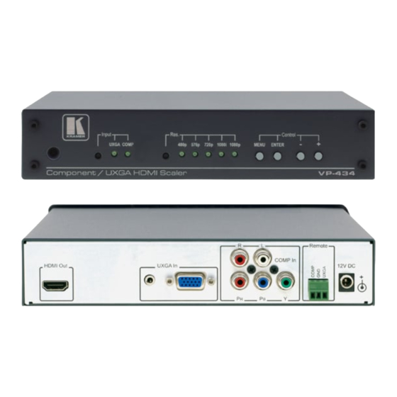
Page 8: Defining The Vp-434 Component/Uxga Hdmi Scaler
Defining the VP-434 Component/UXGA HDMI Scaler This section defines the VP-434. Figure 1: VP-434 Component/UXGA HDMI Scaler Feature Function IR Receiver Receives signals from the remote control transmitter INPUT Selector Button Press to select the UXGA input or the COMP input... - Page 9 For component video, connect all three connectors: Y, Cb, Cr (also known as YUV) Y RCA Connector Remote Contact Closure Pins Connects to a contact closure switch (see Section 12V DC +12V DC connector for powering the unit VP-434 - Overview...
-
Page 10: Connecting The Vp-434
Connecting the VP-434 Always switch off the power to each device before connecting it to your VP-434. After connecting your VP-434, connect its power and then switch on the power to each device. To connect the VP-434 as illustrated in the example in Figure 1. -
Page 11: F Igure 2: Connecting The Vp-434 Component/Uxga Hdmi Scaler
Figure 2: Connecting the VP-434 Component/UXGA HDMI Scaler VP-434 - Connecting the VP-434... -
Page 12: Connecting The Contact Closure Remote Control Pins
DO NOT connect more than one PIN to the GND PIN at the same time To select COMP, To select UXGA, connect the connect the COMP PIN to the UXGA PIN to the GND PIN GND PIN Figure 3: Connecting the Contact Closure Remote Control PINs VP-434 - Connecting the VP-434... -
Page 13: Operating The Vp-434
• Control buttons, including the MENU, ENTER, + and – buttons Using the CONTROL Buttons The CONTROL buttons let you control the VP-434 via the OSD menu. Press the: • MENU button to enter the menu The default timeout is set to 10 seconds •... -
Page 14: The Main Menu
Sets the vertical position of the OSD (from 0 to 100) TIMER Sets the timeout period in seconds (from 5 to 100). The default timeout is 10 seconds BACKGROUND Sets the OSD background between 0 (solid black) and 8 (transparent) VP-434 - Operating the VP-434... -
Page 15: Using The Infrared Remote Control Transmitter
Using the Infrared Remote Control Transmitter You can control the VP-434 from the infrared remote control transmitter, as defined in Figure Keys Function SIZE POWER SIZE Set the size of the image displayed POWER Turn the unit VP-434 ON or OFF... -
Page 16: Technical Specifications
21.5cm x 16.1cm x 4.36cm (8.46” x 6.34” x 1.7”) W, D, H WEIGHT: 1.1kg (2.43lb) approx. ACCESSORIES: Power supply, IR remote control OPTIONS: RK-1 Rack adapter Specifications are subject to change without notice at http://www.kramerelectronics.com VP-434 - Technical Specifications... - Page 17 VP-434 - Technical Specifications...
- Page 18 For the latest information on our products and a list of Kramer distributors, visit our Web site where updates to this user manual may be found. We welcome your questions, comments, and feedback. Web site: www.kramerelectronics.com E-mail: info@kramerel.com SAFETY WARNING...
Need help?
Do you have a question about the VP-434 and is the answer not in the manual?
Questions and answers