Table of Contents
Advertisement
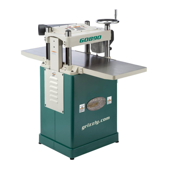
MODEL G0890/G0891
15" FIXED-TABLE PLANERS
OWNER'S MANUAL
(For models manufactured since 06/19)
COPYRIGHT © JULY, 2019 BY GRIZZLY INDUSTRIAL, INC.
WARNING: NO PORTION OF THIS MANUAL MAY BE REPRODUCED IN ANY SHAPE
OR FORM WITHOUT THE WRITTEN APPROVAL OF GRIZZLY INDUSTRIAL, INC.
#MN20544 PRINTED IN TAIWAN
V1.07.19
Advertisement
Table of Contents


Need help?
Do you have a question about the G0890 and is the answer not in the manual?
Questions and answers