Table of Contents
Advertisement
Quick Links
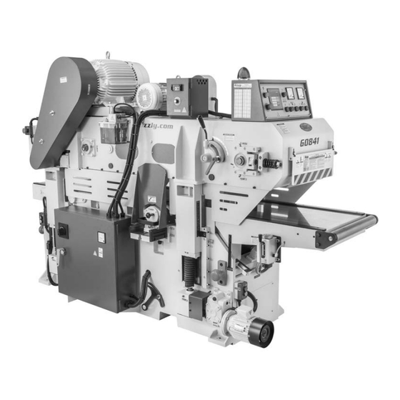
MODEL G0841
18" DOUBLE-SIDED PLANER
w/SPIRAL CUTTERHEADS
OWNER'S MANUAL
(For models manufactured since 06/18)
COPYRIGHT © JULY, 2018 BY GRIZZLY INDUSTRIAL, INC.
WARNING: NO PORTION OF THIS MANUAL MAY BE REPRODUCED IN ANY SHAPE
OR FORM WITHOUT THE WRITTEN APPROVAL OF GRIZZLY INDUSTRIAL, INC.
#ESTK19509 PRINTED IN TAIWAN
V1.07.18
Advertisement
Table of Contents

Related Manuals for Grizzly G0841


Summary of Contents for Grizzly G0841
- Page 1 (For models manufactured since 06/18) COPYRIGHT © JULY, 2018 BY GRIZZLY INDUSTRIAL, INC. WARNING: NO PORTION OF THIS MANUAL MAY BE REPRODUCED IN ANY SHAPE OR FORM WITHOUT THE WRITTEN APPROVAL OF GRIZZLY INDUSTRIAL, INC. #ESTK19509 PRINTED IN TAIWAN V1.07.18...
- Page 2 This manual provides critical safety instructions on the proper setup, operation, maintenance, and service of this machine/tool. Save this document, refer to it often, and use it to instruct other operators. Failure to read, understand and follow the instructions in this manual may result in fire or serious personal injury—including amputation, electrocution, or death.
-
Page 3: Table Of Contents
Table of Contents INTRODUCTION ..........2 SECTION 5: ACCESSORIES ......45 Contact Info............ 2 SECTION 6: MAINTENANCE ......48 Manual Accuracy ........... 2 Schedule ............48 Identification (Front) ........3 Cleaning & Protecting ........49 Identification (Rear)........4 Lubrication ........... 49 Identification (Right) ........ -
Page 4: Introduction
ID label (see below). This information is required for us to provide proper tech support, and it helps us determine if updated documenta- tion is available for your machine. Manufacture Date Serial Number Model G0841 (Mfd. Since 06/18) -
Page 5: Identification (Front)
If normal safety pre- respect. Failure to do so could result in cautions are overlooked or ignored, seri- serious personal injury, damage to equip- ous personal injury may occur. ment, or poor work results. Model G0841 (Mfd. Since 06/18) -
Page 6: Identification (Rear)
Dust Hood w/ 5" Dust Port Pressure Bar Adjustment Bolts Emergency Stop Button (1 of 2) Planer Table Machine Amp Meter Headstock Height Table Main Power Electrical Panel w/ Switch (1 of 2) Guard Switch Lock-Out Handle Model G0841 (Mfd. Since 06/18) -
Page 7: Identification (Right)
Automatic Oiler Chain Serrated Switch Drive Roller Upper Cutterhead Upper Pressure Roller Chain Drive Access Door Lower Pressure Rollers Lower Cutterhead Belt Tension Lever w/Lock Lever Lower Cutterhead 6" Dust Belt Cover Port Model G0841 (Mfd. Since 06/18) -
Page 8: Controls & Components
(i.e., dis- tance from bottom dead center (BDC) of upper E. Automatic Oiler On/Off Switch: Use to turn cutterhead to planer table). automatic oiler system on and off. Always turn ON before starting feed system. Model G0841 (Mfd. Since 06/18) - Page 9 Feed Track on Page 10 for more informa- Example: To enter a final workpiece thick- tion). ness of 2 ⁄ ", press key, then press follow- ing keys: , and then press key. • Model G0841 (Mfd. Since 06/18)
- Page 10 AN. Serrated & Upper Pressure Roller Adjustment Rods (2 of 4): Adjust rods to set serrated and upper pressure roller height. Jam nuts lock adjustment rods in position. Model G0841 (Mfd. Since 06/18)
- Page 11 BB. 6" Dust Port: Provides connection to dust- AU. Electrical Panel w/Lock-out Handle: collection system. Provides access to machine wiring for initial setup. Lock-out handle is easily removable to prevent unauthorized access. Model G0841 (Mfd. Since 06/18)
-
Page 12: Internal Components
M. Lower Pressure Roller: Chain-driven roll- Idler Roller: Spring-loaded idler roller that er that pulls workpieces through the upper cutterhead. holds workpieces down as they are fed toward serrated roller. -10- Model G0841 (Mfd. Since 06/18) -
Page 13: Machine Data Sheet
Bearings ........................Sealed & Permanently Lubricated Lower Cutterhead Horsepower ................................10 HP Phase .................................. 3-Phase Amps ..................................23A Speed ................................1760 RPM Type ................................TEFC Induction Power Transfer ..............................Belt Drive Bearings ........................Sealed & Permanently Lubricated -11- Model G0841 (Mfd. Since 06/18) Model G0841 Page 1 of 3... - Page 14 Number of Indexable Cutters ............................114 Cutter Insert Type ..........................Indexable Carbide Cutter Insert Size Length ............................15 mm Cutter Insert Size Width ............................15 mm Cutter Insert Size Thickness ..........................2.5 mm -12- Model G0841 (Mfd. Since 06/18) Page 2 of 3 Model G0841...
- Page 15 Hex Wrench Set: 1.5, 2, 2.5, 3, 4. 5, 5.5, 6, 8, 10mm T-Handle Hex Wrench 4mm Replacement Carbide Inserts 15 x15 x 2.5mm (10) Torx Head Screws M6-1 x 12 (20) Block Gauge -13- Model G0841 (Mfd. Since 06/18) Model G0841 Page 3 of 3...
-
Page 16: Section 1: Safety
Everyday ery. Never operate under the influence of drugs or eyeglasses are NOT approved safety glasses. alcohol, when tired, or when distracted. -14- Model G0841 (Mfd. Since 06/18) - Page 17 Make sure they are properly installed, you experience difficulties performing the intend- undamaged, and working correctly BEFORE ed operation, stop using the machine! Contact our operating machine. Technical Support at (570) 546-9663. -15- Model G0841 (Mfd. Since 06/18)
-
Page 18: Additional Safety For Double-Sided Planers
⁄ " side- or tipping. For long stock, use auxiliary support by-side at same time. stands on infeed and outfeed ends of machine. -16- Model G0841 (Mfd. Since 06/18) -
Page 19: Section 2: Power Supply
To reduce the risk of these hazards, avoid over- loading the machine during operation and make sure it is connected to a power supply circuit that meets the specified circuit requirements. -17- Model G0841 (Mfd. Since 06/18) - Page 20 DO NOT use a phase converter to sup- ply 3-Phase power, as it could damage or decrease life of electrical components. Damage caused by running this machine with a phase converter will not be covered under warranty. -18- Model G0841 (Mfd. Since 06/18)
-
Page 21: Section 3: Setup
Keep children and pets away you are completely satisfied with the machine and from plastic bags or packing have resolved any issues between Grizzly or the materials shipped with this shipping agent. You MUST have the original pack- machine. Discard immediately. -
Page 22: Inventory
If you cannot find an item on this list, care- fully check around/inside the machine and packaging materials. Often, these items get lost in packaging materials while unpack- ing or they are pre-installed at the factory. -20- Model G0841 (Mfd. Since 06/18) -
Page 23: Cleanup
Figure 12. T23692 Orange Power Degreaser. then wipe off the rest with the rag. Repeat Steps 2–3 as necessary until clean, then coat all unpainted surfaces with a quality metal protectant to prevent rust. Aluminum -21- Model G0841 (Mfd. Since 06/18) -
Page 24: Site Considerations
108" = Electrical Connection Feed Direction 79" Keep Infeed Keep Outfeed 39" Area Unobstructed Area Unobstructed Min. 48" for Maintenance Wall Figure 13. Minimum working clearances. -22- Model G0841 (Mfd. Since 06/18) -
Page 25: Lifting & Placing
To lift and place machine: Move machine near its prepared location while still inside shipping crate. Remove top and sides of shipping crate, then place small items aside in safe location. Cleats Figure 15. Location of lifting cleats. -23- Model G0841 (Mfd. Since 06/18) -
Page 26: Leveling
Insert (4) M16-1.5 x 75 hex bolts with (4) M16- 1.5 jam nuts into (4) threaded holes in foot- ings, as shown in Figure 17. Hex Bolt Threaded Jam Nut Hole Footing Leveling Pad Figure 17. Leveling hardware orientation (1 of 4). -24- Model G0841 (Mfd. Since 06/18) -
Page 27: Assembly
Figure 19. Adjust limit switch so trigger just touches pressure bar when fully extended (see Figure 19). Limit Switch Figure 18. Model H2683 Master Machinist's Level. Trigger Pressure Figure 19. Attaching pressure bar limit switch. -25- Model G0841 (Mfd. Since 06/18) -
Page 28: Lubricating Machine
Hose Clamp 6" Hose 5" Hose Hose Clamp Figure 20. Dust hoses attached to dust ports. Tug hoses to make sure they do not come off. A tight fit is necessary for proper performance. -26- Model G0841 (Mfd. Since 06/18) -
Page 29: Power Connection
Electrical Electrical Panel Note: Lock the switch in the OFF position to Panel Door restrict others from starting the machine. Figure 23. Electrical panel opened. Figure 22. Disconnecting power from machine. -27- Model G0841 (Mfd. Since 06/18) -
Page 30: Test Run
Figure 25), then connect incoming power machine until the information is understood. wires to power terminals (see Figure 25). (Refer to G0841 Wiring Manual for detailed wiring diagrams.) DO NOT start machine until all preceding setup instructions have been performed. - Page 31 (refer to Figure 25 on Page 28), then restart Test Run. Figure 27. Resetting the Emergency Stop button. Push power button (see Figure 28) to enable power to all motors and electrical systems. Power Button Figure 28. Location of power button. -29- Model G0841 (Mfd. Since 06/18)
- Page 32 Call Tech Support for help. 16. Twist Emergency Stop button on control panel clockwise until it pops out (see Figure 27 on Page 29). This resets button so machine will start. -30- Model G0841 (Mfd. Since 06/18)
-
Page 33: Tightening Belts
A buildup of black belt dust at the bottom of the Page 29) to enable power to all motors and belt cover is normal during the life of the machine electrical systems. and does not indicate a problem with the machine or belts. -31- Model G0841 (Mfd. Since 06/18) -
Page 34: Section 4: Operations
Regardless of the content in this sec- tion, Grizzly Industrial will not be held liable 12. When all safety precautions have been taken, for accidents caused by lack of training. -
Page 35: Planing Tips
Your inserts will remain sharp much longer. Alternatively, plane multiple workpieces of similar thicknesses side-by- side. The Model G0841 is not designed to flat- ten excessively cupped, bowed, or twisted • To avoid "chip marks," always plane WITH stock. -
Page 36: Workpiece Inspection
" excessive cupping, bowing, or twisting are dangerous to plane because they are unsta- " ble and often unpredictable when being planed. DO NOT use workpieces with these characteristics! Figure 36. Minimum stock dimensions. -34- Model G0841 (Mfd. Since 06/18) -
Page 37: Wood Types
Basswood ing is completed. Eastern White Pine Balsa Figure 37. Janka Hardness Rating for some common wood species. -35- Model G0841 (Mfd. Since 06/18) -
Page 38: Setting Depth Of Cut (Lower Cutterhead)
Problem: Regularly spaced indentations across Figure 39. Location of infeed table handwheel face of workpiece are caused by excessive roller and depth-of-cut scale. pressure or excessive feed rate. Solution: Reduce roller pressure; reduce feed rate. -36- Model G0841 (Mfd. Since 06/18) -
Page 39: Setting Depth Of Cut (Upper Cutterhead)
• Use the digital control pad on the con- trol panel (see Figure 42) to enter a final workpiece thickness. Figure 40. G2857 Thickness Gauge. Digital Controls Figure 42. Location of digital controls. -37- Model G0841 (Mfd. Since 06/18) -
Page 40: Adjusting Infeed Safety Guard
Infeed Safety Emergency Guard Stop Plate Figure 45. Infeed safety guard and components. -38- Model G0841 (Mfd. Since 06/18) -
Page 41: Using Digital Controls
The digital control pad functions in standard and metric units of measure. Press the (UNIT) key UNIT to toggle between inches and millimeters. The active unit of measure (INCH or MM) is highlight- ed in the digital controls (see Figure 46). -39- Model G0841 (Mfd. Since 06/18) - Page 42 Use number (0–9) and decimal (.) keys to enter value. For example, to enter final workpiece thickness of 2 ⁄ ", press the following keys: . Value flashes on digital readout • as it is entered. -40- Model G0841 (Mfd. Since 06/18)
-
Page 43: Setting Feed Rate
Setting Feed Rate Adjusting Feed Track Pressure setting feed rate The Model G0841 feed system includes a feed track, serrated roller, three pressure rollers, and a adjusting feed belt pressure If you notice the feed track slipping on workpieces chain drive. The feed system moves workpieces... -
Page 44: Rotating/Replacing Cutterhead Inserts
Heavy Leather Gloves ........1 Pair T26685 or ISO 32 Equivalent Oil ..As Needed Paint Pen (Optional) .......... 1 Hex Bolt Hex Nut Figure 50. Location of lower cutterhead hex bolt and hex nut. -42- Model G0841 (Mfd. Since 06/18) - Page 45 15. Tension V-belts (refer to Steps 3–4 of Tensioning Lower Cutterhead V-Belts on Cutterhead Page 59 for instructions). Insert 16. Close lower cutterhead belt cover and chain drive access door. Figure 52. Location of lower cutterhead inserts and Torx screws. -43- Model G0841 (Mfd. Since 06/18)
- Page 46 (see Figure 54) to secure cutterhead while cleaning, rotating, and replacing inserts. Thoroughly clean away all sawdust or debris from top of insert, Torx screw, and surround- ing area (see Figure 55). -44- Model G0841 (Mfd. Since 06/18)
-
Page 47: Section 5: Accessories
SECTION 5: ACCESSORIES accessories T28770—Indexable Carbide Inserts, 10 Pk. Each insert in this 10-pack of Grizzly replace- ment indexable carbide inserts measures Installing unapproved accessories may 15 x 15 x 2.5mm. cause machine to malfunction, resulting in serious personal injury or machine damage. - Page 48 D2273 D2274 Figure 60. Models D2273 and D2274 Roller Stands. Figure 61. Model G0683HEP 10 HP Cyclone Dust Collector. www.grizzly.com 1-800-523-4777 order online at or call -46- Model G0841 (Mfd. Since 06/18)
- Page 49 H4978 T20446 H4979 Figure 65. T21272 Golden Pigskin Gloves. Figure 63. Hearing protection assortment. www.grizzly.com 1-800-523-4777 order online at or call -47- Model G0841 (Mfd. Since 06/18)
-
Page 50: Section 6: Maintenance
(see Page 51). Lubricate elevation slideways (see Page 52). • • Lubricate chipbreaker segments (see Page 52). • Lubricate chipbreaker/pressure bar hinges (see Page 52). • Blow dust out of motor fans with compressed air. -48- Model G0841 (Mfd. Since 06/18) -
Page 51: Cleaning & Protecting
Use the information in the charts below as a guide for lubrication tasks. We recommend using cleaning protecting Cleaning the Model G0841 is relatively easy. Grizzly Model T23962, T23963, and T23964 lubri- Vacuum excess wood chips and sawdust, and cants for most of the lubrication tasks. - Page 52 Elevation Screw NLGI #2 1 Pump cated on reservoir. Bearings Table Roller Bearings NLGI #2 1 Pump ISO 320 Feed System Gear box 74 oz. (T28042) ISO 320 Elevation Gearbox 17 oz. (T28042) -50- Model G0841 (Mfd. Since 06/18)
- Page 53 Chain Drive Chain Drive Grease Fittings Chain Drive Chain Figure 72. Location of feed track roller bearings Drive grease fittings—leftside. Figure 70. Location of chain drive. -51- Model G0841 (Mfd. Since 06/18)
- Page 54 Reinstall and Elevation Slideways refill oil cup after oil passage is cleared. Oiling Cups (2 of 8) Figure 74. Location of elevation slideway oiling cups (2 of 8). -52- Model G0841 (Mfd. Since 06/18)
- Page 55 Rightside Leftside Upper Cutterhead Bearings Grease Fittings Figure 79. Location of upper cutterhead grease fittings. Infeed Table Slideway Oiling Cups Figure 77. Location of infeed table slideway oiling cups. -53- Model G0841 (Mfd. Since 06/18)
- Page 56 To access the leadscrews, raise the headstock to at least 7" and lift the leadscrew boots, as shown in Figure 81. Re-attach boots when done. -54- Model G0841 (Mfd. Since 06/18)
- Page 57 10 seconds to allow oil to settle in sight glass before taking a reading. Wipe away any excess oil, then clean and replace vented fill plug. Clear vented fill plug with low-pressure compressed air if clogged. -55- Model G0841 (Mfd. Since 06/18)
-
Page 58: Section 7: Service
1. Contact certified electrician for repair. fuse/breaker 2. Power supply circuit undersized for machine 2. Ensure proper power supply; replace fuse/breaker; immediately or fuse/breaker at fault. contact certified electrician for repair. trips after startup. -56- Model G0841 (Mfd. Since 06/18) - Page 59 2. Increase elevation chain tension (Page 77). 2. Slack in elevation chain. thickness value. 3. Reset headstock height (Page 70). 3. Digital controls and headstock height not synchronized. -57- Model G0841 (Mfd. Since 06/18)
- Page 60 1. Ensure workpiece is suitable for planing (Page 34). Workpiece remains 1. Workpiece excessively bowed or warped, concave or convex and is not suitable for planing. along its length after planing. -58- Model G0841 (Mfd. Since 06/18)
-
Page 61: Tensioning/Replacing V-Belts
Tension maximum overall life of the V-belts. It is nor- Belt Cover Lock Lever mal to see a small build-up of rubber dust during the break-in period. Figure 85. Location of lower cutterhead V-belts. -59- Model G0841 (Mfd. Since 06/18) - Page 62 Loosen hex nuts on hex bolts that secure Once V-belts are properly tensioned, tighten motor to mounting plate (see Figure 88). jam nuts and hex nuts to secure motor in position. 10. Replace upper cutterhead belt cover. -60- Model G0841 (Mfd. Since 06/18)
- Page 63 Tensioning Lower Cutterhead V-Belts on Hex Nuts Hex Nuts Page 59 for instructions). Re-install lower cutterhead belt cover and close chain drive access door. Mounting Plate Figure 92. Location of upper cutterhead motor mounting hardware. -61- Model G0841 (Mfd. Since 06/18)
-
Page 64: Checking/Adjusting Pulley Alignment
Tensioning Upper Cutterhead V-Belts on Pulley Page 60). Alignment 11. Once V-belts are properly tensioned, tighten jam nuts to secure motor in position. Motor 12. Re-install upper cutterhead belt cover. Pulley Figure 94. Pulleys correctly aligned. -62- Model G0841 (Mfd. Since 06/18) - Page 65 Adjust set screw and move lower cutterhead to align cutterhead pulley with motor pulley. Tighten jam nut to secure lower cutterhead in position. Replace lower cutterhead belt cover and close chain drive access door. -63- Model G0841 (Mfd. Since 06/18)
-
Page 66: Aligning Lower Cutterhead Height
11. Re-install upper cutterhead belt cover. insert is at top dead center (its highest point during rotation), as shown in Figure 99. Top Dead Center Figure 99. Cutterhead insert at top dead center. Bottom Dead -64- Model G0841 (Mfd. Since 06/18) Center... - Page 67 — If cutterhead height is correctly set, no adjustments are necessary. — If cutterhead inserts lift block gauge off planer table or are below block gauge, then cutterhead height must be reset. -65- Model G0841 (Mfd. Since 06/18)
-
Page 68: Calibrating Lower Cutterhead Depth Of Cut
Scale Place block gauge across infeed and planer tables, as shown in Figure 103. Figure 104. Adjusting scale pointer to " 0 ". Note: Make sure side B of block gauge is face down. -66- Model G0841 (Mfd. Since 06/18) -
Page 69: Setting Upper Cutterhead At Bdc
AT POWER SOURCE! Remove upper cutterhead belt cover and open chain drive access door. Use upper cutterhead pulley to rotate cutterhead so insert on edge of cutterhead is close to BDC. Connect machine to power. -67- Model G0841 (Mfd. Since 06/18) -
Page 70: Squaring Headstock
Set headstock height to 4". Tighten (4) cap screws securing elevation leadscrew collars. DISCONNECT AND LOCK-OUT MACHINE AT POWER SOURCE! Set headstock height. (Refer to Setting Headstock Height on Page 70.) -68- Model G0841 (Mfd. Since 06/18) - Page 71 Turn elevation leadscrew collar (see Figure 107 on Page 68) counterclockwise until inserts on leftside and rightside edge of upper cutterhead are at BDC, and then tighten (2) cap screws securing elevation leadscrew collar. -69- Model G0841 (Mfd. Since 06/18)
-
Page 72: Setting Headstock Height
(SET) key on digital control pad and enter same value entered in Step 4. Press and hold (SET) key for three seconds. Entered value is now displayed as current height. Run another test workpiece through machine to verify setting. -70- Model G0841 (Mfd. Since 06/18) - Page 73 If needed, repeat Steps 3–7 until entire idler table underneath left-side of idler roller (see roller height is correct. Figure 111). Bottom of Idler Roller Planer Rotacator Table Figure 111. Rotacator placed underneath left- side of idler roller. -71- Model G0841 (Mfd. Since 06/18)
- Page 74 (see Figure 114). If needed, repeat Steps 3–7 until entire ser- rated roller height is correct. Bottom of Serrated Roller Planer Rotacator Table Figure 114. Rotacator placed underneath leftside of serrated roller -72- Model G0841 (Mfd. Since 06/18)
- Page 75 Repeat Steps 3–6 on remaining 8 chip- breaker segments. Place Rotacator or dial indicator on planer table underneath first chipbreaker segment (see Figure 117). Bottom of First Chipbreaker Segment Planer Table Rotacator Figure 117. Rotacator placed underneath first chipbreaker segment. -73- Model G0841 (Mfd. Since 06/18)
- Page 76 If needed, repeat Steps 3–7 until entire pres- (see Figure 120). sure bar height is correct. Rotacator Bottom of Pressure Bar Planer Table Figure 120. Rotacator placed underneath left- side of pressure bar. -74- Model G0841 (Mfd. Since 06/18)
- Page 77 (see Figure 123). If needed, repeat Steps 4–6 until upper pres- sure roller height is correct. Rotacator Bottom of Upper Pressure Roller Planer Table Figure 123. Rotacator placed underneath left- side of upper pressure roller. -75- Model G0841 (Mfd. Since 06/18)
- Page 78 — If block gauge does not lay flat across planer table or does not move when pres- sure roller is rocked back and forth, then adjust height of lower pressure roller. Proceed to Step 6. -76- Model G0841 (Mfd. Since 06/18)
-
Page 79: Tensioning Elevation Chain
Repeat Steps 4–8 on rear lower pressure roller. Elevation Chain 10. If needed, repeat Steps 4–9 until front and Tension Bolt rear lower pressure roller height is correct. Figure 130. Location of elevation chain tension bolt. -77- Model G0841 (Mfd. Since 06/18) -
Page 80: Tensioning Feed Track
If you notice the feed track is sion is achieved. sagging and making a "slapping" sound during operation, the feed track may require tensioning. Item(s) Needed: Wrench Open-Ends or Socket 27mm ....1 Calipers ............. 1 -78- Model G0841 (Mfd. Since 06/18) - Page 81 Would you recommend Grizzly Industrial to a friend? _____ Yes _____No Would you allow us to use your name as a reference for Grizzly customers in your area? Note: We never use names more than 3 times. _____ Yes _____No 10.
- Page 82 FOLD ALONG DOTTED LINE Place Stamp Here GRIZZLY INDUSTRIAL, INC. P.O. BOX 2069 BELLINGHAM, WA 98227-2069 FOLD ALONG DOTTED LINE Send a Grizzly Catalog to a friend: Name_______________________________ Street_______________________________ City______________State______Zip______ TAPE ALONG EDGES--PLEASE DO NOT STAPLE...
-
Page 83: Warranty & Returns
WARRANTY & RETURNS Grizzly Industrial, Inc. warrants every product it sells for a period of 1 year to the original purchaser from the date of purchase. This warranty does not apply to defects due directly or indirectly to misuse, abuse, negligence, accidents, repairs or alterations or lack of maintenance.
Need help?
Do you have a question about the G0841 and is the answer not in the manual?
Questions and answers