Table of Contents
Advertisement
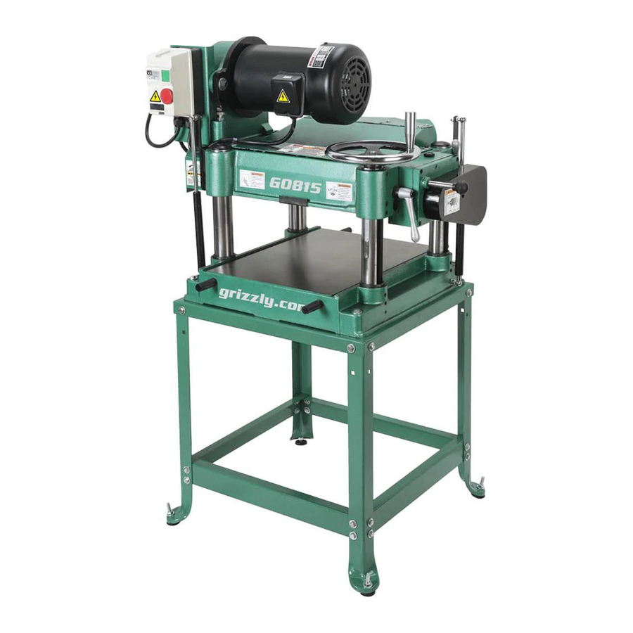
MODEL G0815
15" HEAVY-DUTY PLANER
OWNER'S MANUAL
(For models manufactured since 09/18)
Shown with optional stand:
Model T27650
177335
COPYRIGHT © FEBRUARY, 2016 BY GRIZZLY INDUSTRIAL, INC., REVISED DECEMBER, 2018 (MN)
WARNING: NO PORTION OF THIS MANUAL MAY BE REPRODUCED IN ANY SHAPE
OR FORM WITHOUT THE WRITTEN APPROVAL OF GRIZZLY INDUSTRIAL, INC.
#WK17990 PRINTED IN TAIWAN
V2.12.18
Advertisement
Table of Contents

Related Manuals for Grizzly G0815


Summary of Contents for Grizzly G0815
- Page 1 Shown with optional stand: Model T27650 177335 COPYRIGHT © FEBRUARY, 2016 BY GRIZZLY INDUSTRIAL, INC., REVISED DECEMBER, 2018 (MN) WARNING: NO PORTION OF THIS MANUAL MAY BE REPRODUCED IN ANY SHAPE OR FORM WITHOUT THE WRITTEN APPROVAL OF GRIZZLY INDUSTRIAL, INC.
- Page 2 This manual provides critical safety instructions on the proper setup, operation, maintenance, and service of this machine/tool. Save this document, refer to it often, and use it to instruct other operators. Failure to read, understand and follow the instructions in this manual may result in fire or serious personal injury—including amputation, electrocution, or death.
-
Page 3: Table Of Contents
Table of Contents INTRODUCTION ..........2 SECTION 5: ACCESSORIES ......27 Contact Info............ 2 SECTION 6: MAINTENANCE ......31 Manual Accuracy ........... 2 Schedule ............31 Identification ........... 3 Cleaning & Protecting ........31 Controls & Components ......... 4 Lubrication ........... 32 Internal Components........ -
Page 4: Introduction
ID label (see below). This information is required for us to provide proper tech support, and it helps us determine if updated documenta- tion is available for your machine. Manufacture Date Serial Number Model G0815 (Mfd. Since 09/18) -
Page 5: Identification
Gearbox Gas Spring Table Feed Rate Control Knob Column Locks Lifting Headstock (1 of 2) Bars Height Scale (2 of 4) To reduce your risk of serious injury, read this entire manual BEFORE using machine. Model G0815 (Mfd. Since 09/18) -
Page 6: Controls & Components
C. Feed Rate Control Knob: Selects 30 FPM feed rate when pushed in, and 16 FPM feed Note: Headstock height MUST be properly rate when pulled out. adjusted for anti-kickback fingers to function. Model G0815 (Mfd. Since 09/18) -
Page 7: Internal Components
Use this machine with respect and caution to decrease the risk of operator injury. If normal safety precautions are overlooked or ignored, serious personal injury may occur. Model G0815 (Mfd. Since 09/18) -
Page 8: Machine Data Sheet
MACHINE DATA SHEET Customer Service #: (570) 546-9663 · To Order Call: (800) 523-4777 · Fax #: (800) 438-5901 MODEL G0815 15" 3 HP HEAVY‐DUTY PLANER Product Dimensions: Weight................................350 lbs. Width (side-to-side) x Depth (front-to-back) x Height..............32 x 28 x 23-1/2 in. - Page 9 Drive Gears Run in Oil Bath Accessories Included: Knife-Setting Jig Accessories Recommended: T27650 Planer Stand for G0815 The information contained herein is deemed accurate as of 6/4/2019 and represents our most recent product specifications. Model G0815 PAGE 2 OF 2 Due to our ongoing improvement efforts, this information may not accurately describe items previously purchased.
-
Page 10: Section 1: Safety
Never operate under the influence of drugs or injury or blindness from flying particles. Everyday alcohol, when tired, or when distracted. eyeglasses are NOT approved safety glasses. Model G0815 (Mfd. Since 09/18) - Page 11 Make sure they are properly installed, you experience difficulties performing the intend- undamaged, and working correctly BEFORE ed operation, stop using the machine! Contact our operating machine. Technical Support at (570) 546-9663. Model G0815 (Mfd. Since 09/18)
-
Page 12: Additional Safety For Planers
GRAIN DIRECTION. Planing across the grain adjusted before operation. is hard on the planer and may cause kickback. Plane in the same direction or at a slight angle with the wood grain. -10- Model G0815 (Mfd. Since 09/18) -
Page 13: Section 2: Power Supply
To reduce the risk of these hazards, avoid over- loading the machine during operation and make sure it is connected to a power supply circuit that meets the specified circuit requirements. -11- Model G0815 (Mfd. Since 09/18) - Page 14 Minimum Gauge Size ......12 AWG all local codes and ordinances. Maximum Length (Shorter is Better)..50 ft. -12- Model G0815 (Mfd. Since 09/18)
-
Page 15: Section 3: Setup
IMPORTANT: Save all packaging materials until weight of this machine. you are completely satisfied with the machine and have resolved any issues between Grizzly or the shipping agent. You MUST have the original pack- aging to file a freight claim. It is also extremely helpful if you need to return your machine later. -
Page 16: Inventory
E. Feed Rate Control Knob ⁄ -16 ....1 Open-End Wrenches 8/10, 12/14mm ...1 Ea. G. T-Handle Hex Wrench 5mm ....... 1 H. Hex Wrenches 2.5, 3, 4, 6mm ....1 Ea. Figure 6. Model G0815 loose inventory. -14- Model G0815 (Mfd. Since 09/18) - Page 17 Repeat Steps 2–3 as necessary until clean, then coat all unpainted surfaces with a quality metal protectant to prevent rust. -15- Model G0815 (Mfd. Since 09/18)
-
Page 18: Site Considerations
Shadows, glare, or strobe effects that may distract access restricted location. or impede the operator must be eliminated. Wall Min. 30" for Maintenance = Electrical Connection Illustration Not To Scale 32" Figure 7. Minimum working clearances. -16- Model G0815 (Mfd. Since 09/18) -
Page 19: Lifting & Placing
(1 of 4) Reach Under Here Figure 8. Machine on shipping pallet, and lifting bar inserted into hole in base (1 of 4 shown). Figure 10. Lifting planer with forklift. Set planer down on intended location. -17- Model G0815 (Mfd. Since 09/18) -
Page 20: Bench Mounting
Another option is a "direct mount" (see example below) where the machine is secured directly to the workbench with lag screws and washers. Lag Screw Flat Washer Machine Base Workbench Figure 12. "Direct Mount" setup. -18- Model G0815 (Mfd. Since 09/18) -
Page 21: Assembly
Tug the hose to make sure it does not come off. Note: A tight fit is necessary for proper performance. Dust Hood Figure 15. Dust hood installed. Figure 16. Dust hose attached to dust port. -19- Model G0815 (Mfd. Since 09/18) -
Page 22: Test Run
Press STOP button (see Figure 17) to turn ed results that can lead to serious injury, machine OFF. death, or machine/property damage. Congratulations! The Test Run is complete. -20- Model G0815 (Mfd. Since 09/18) -
Page 23: Section 4: Operations
Read books/magazines or get OFF. formal training before beginning any proj- ects. Regardless of the content in this sec- tion, Grizzly Industrial will not be held liable for accidents caused by lack of training. -21- Model G0815 (Mfd. Since 09/18) -
Page 24: Workpiece Inspection
On the contrary, Figure 18. Janka Hardness Rating for some a workpiece supported on the bowed side common wood species. will rock during operation and could cause severe injury from kickback. -22- Model G0815 (Mfd. Since 09/18) -
Page 25: Planing Tips
• Always true cupped or warped stock on a excess after planing is completed. jointer before planing. -23- Model G0815 (Mfd. Since 09/18) -
Page 26: Depth Of Cut
Rippled Cut Problem: Regularly spaced indentations across Figure 19. Depth-of-cut indicator and scale. face of workpiece are caused by excessive outfeed roller pressure or excessive feed rate. Solution: Reduce outfeed roller pressure; reduce feed rate. -24- Model G0815 (Mfd. Since 09/18) -
Page 27: Setting Feed Rate
Figure 20. Feed rate control knob positions. The knife-setting jig that is included with the Model G0815 is designed to set the knives 0.049" NOTICE higher than the cutterhead surface. Only change the feed rate when the planer... - Page 28 Figure 22. Figure 24. Gib bolt tightening sequence. Repeat Step 8, snugging gib bolts a little more. 10. Repeat Step 8, this time fully tightening all gib bolts. 11. Repeat Steps 4–8 for remaining knives. -26- Model G0815 (Mfd. Since 09/18)
-
Page 29: Section 5: Accessories
T27650—Planer Stand for G0815 An open-frame stand designed especially for the G0815 15" Benchtop Planer. An excellent choice if you have the floor space but not the benchtop space for this machine. Figure 26. G2790 Universal Knife Grinder. - Page 30 Note: When buying planer pals, follow this simple guideline: 15" to 20" Planers —use 2 jigs. Over 20" Planers—use 3 jigs. Figure 31. H7723 60" Birch Workbench. Figure 29. W1216A Planer Pals, Standard Pair. www.grizzly.com 1-800-523-4777 order online at or call -28- Model G0815 (Mfd. Since 09/18)
- Page 31 Adjustable in height from 26 ⁄ " to ⁄ ". Approximate shipping weight: 62 lbs. 1000 Lb. Capacity! Figure 35. T26979 3-in-1 Workpiece Support Stand. Figure 33. D2271 Roller Table. www.grizzly.com 1-800-523-4777 order online at or call -29- Model G0815 (Mfd. Since 09/18)
- Page 32 Especially important if you or employees operate for hours at a time. H4978 T20446 H4979 Figure 39. Recommended products for protecting unpainted cast iron/steel parts on machinery. Figure 37. Hearing protection. www.grizzly.com 1-800-523-4777 order online at or call -30- Model G0815 (Mfd. Since 09/18)
-
Page 33: Section 6: Maintenance
Check/tension/replace V-belts (Page 37). • Clean/vacuum dust buildup from inside cabi- net and off motor. • Lubricate height chain sprockets (Page 33). Lubricate drive chain and sprockets (Page 34). • Yearly: Change gearbox oil (Page 34). • -31- Model G0815 (Mfd. Since 09/18) -
Page 34: Lubrication
The bearings are standard sizes and can be replaced through Grizzly. Follow the maintenance schedule on Page 31 and the following procedures to properly lubricate the other planer components, which are essential for long life and trouble-free operation of your planer. -32- Model G0815 (Mfd. Since 09/18) - Page 35 Move the headstock up and down to distribute the lubricant. Column Column Leadscrew (1 of 4) (1 of 4) Figure 43. Height chain and sprockets as viewed from underneath the base. Figure 42. Location of column dust sleeve. -33- Model G0815 (Mfd. Since 09/18)
- Page 36 4 oz. of ISO 320 or equivalent oil. Replace the fill plug (see Figure 46). Figure 44. Location of drive chain and sprockets. Drain Plug Figure 45. Gearbox drain plug. Fill Plug Figure 46. Gearbox fill plug. -34- Model G0815 (Mfd. Since 09/18)
-
Page 37: Section 7: Service
6. Resharpen/replace knives; set knife alignment/ height correctly (Page 25). 7. Motor bearings at fault. 7. Test by rotating shaft; rotational grinding/loose shaft requires bearing replacement. 8. Cutterhead bearings at fault. 8. Replace bearing(s). -35- Model G0815 (Mfd. Since 09/18) - Page 38 2. Feed rate set too slow. 3. Increase depth of cut (Page 24). 3. Cutting depth too shallow. 1. Adjust feed rollers (Page 39). If workpiece twists in 1. Feed rollers not parallel with table. machine. -36- Model G0815 (Mfd. Since 09/18)
-
Page 39: Tensioning/Replacing V-Belts
Motor Mount Belt Tension Phillips Screwdriver #2 ........1 Screw (1 of 2) Adjustment Bolt Hex Wrench 8mm ..........1 Open-End Wrench 14, 17mm ......1 Ea. Belt Tension Jam nut Figure 48. Belt tension controls. -37- Model G0815 (Mfd. Since 09/18) -
Page 40: Tensioning Height Chain
(refer to Height Chain & Sprockets on Page 33 for detailed instructions). NOTICE DO NOT let chain fall off sprockets. It can be very difficult to return chain to its proper location on sprockets without changing table adjustments. -38- Model G0815 (Mfd. Since 09/18) -
Page 41: Feed Rollers & Chip Breaker Heights
(Bottom Dead Center) A & B Figure 52. Example if using a Rotacator to find Infeed Outfeed BDC of knife edge. Roller Roller Figure 51. Planer component recommended clearances (illustration is not to scale). -39- Model G0815 (Mfd. Since 09/18) - Page 42 BDC of cutterhead knife, then retighten both jam nuts. 11. Keeping same "0" reference on Rotacator dial from Step 5, repeat Steps 7–10 for outfeed roller, but adjust it until it is 0.020" below BDC of cutterhead knife. -40- Model G0815 (Mfd. Since 09/18)
- Page 43 Jam Nut illustrated in Figure 55. & Cap Screw 36" Figure 56. Feeler gauge location for adjusting infeed roller height when using wood blocks. Figure 55. Wood blocks properly positioned on the planer table. -41- Model G0815 (Mfd. Since 09/18)
-
Page 44: Adjusting Roller Spring Tension
Hex Wrench 6mm ..........1 To adjust roller spring tension: DISCONNECT MACHINE FROM POWER! Rotate tension screws clockwise to increase tension, and counterclockwise to decrease tension (see Figure 58). Tension Screws Figure 58. Roller spring tension adjustment screws. -42- Model G0815 (Mfd. Since 09/18) -
Page 45: Positioning Chip Deflector
⁄ "– ⁄ ", personal injury. then loosen flange screws that secure chip deflector and adjust gap to ⁄ "– ⁄ ". Retighten flange screws, then replace belt covers, top cover, and dust hood. -43- Model G0815 (Mfd. Since 09/18) -
Page 46: Section 8: Wiring
Technical Support at (570) 546-9663. The photos and diagrams included in this section are best viewed in color. You can view these pages in color at www.grizzly.com. -44- Model G0815 (Mfd. Since 09/18) -
Page 47: Wiring Diagram
Figure 61. Magnetic switch with cover removed. T1/2 T2/4 T3/6 SET @ 14A Relay RA-20 Ground 6-20 Plug Start Capacitor CD60 600MFD 125VAC Motor Figure 62. Motor wiring. READ ELECTRICAL SAFETY -45- Model G0815 (Mfd. Since 09/18) ON PAGE 44! -
Page 48: Section 9: Parts
SECTION 9: PARTS We do our best to stock replacement parts when possible, but we cannot guarantee that all parts shown are available for purchase. Call (800) 523-4777 or visit www.grizzly.com/parts to check for availability. Main 22 56 16 17... - Page 49 KEY 5 X 5 X 30 41-3 P0815041-3 OL RELAY SDE RA-20 12-18A P0815099 CHAIN COVER PLATE P0815042 SET SCREW 5/16-18 X 1/2 P0815100 CAP SCREW 5/16-18 X 1 P0815043 CAP SCREW 1/4-20 X 5/8 -47- Model G0815 (Mfd. Since 09/18)
- Page 50 P0815152 SET SCREW 1/4-20 X 3/4 P0815121 KNIFE ADJUSTMENT SEAT P0815153 EXT RETAINING RING 20MM P0815122 JACK SCREW M5-.8 X 12 P0815154 LOCK WASHER 3/8 P0815123 PLANER KNIVES 15" X 1" X 1/8" 3-PK -48- Model G0815 (Mfd. Since 09/18)
-
Page 51: Table & Columns
216V2 P0815216V2 GAS SPRING BRACKET (REAR) V2.09.18 P0815236 FLAT WASHER 8MM P0815217 SET SCREW 3/8-16 X 1/2 P0815237 HEX NUT M8-1.25 P0815218 HEIGHT CHAIN #410 X 134 P0815238 GAS SPRING BALL JOINT M8-1.25 X 14 -49- Model G0815 (Mfd. Since 09/18) -
Page 52: Labels & Cosmetics
Safety labels help reduce the risk of serious injury caused by machine hazards. If any label comes off or becomes unreadable, the owner of this machine MUST replace it in the original location before resuming operations. For replacements, contact (800) 523-4777 or www.grizzly.com. -50-... - Page 53 Would you recommend Grizzly Industrial to a friend? _____ Yes _____No Would you allow us to use your name as a reference for Grizzly customers in your area? Note: We never use names more than 3 times. _____ Yes _____No 10.
- Page 54 FOLD ALONG DOTTED LINE Place Stamp Here GRIZZLY INDUSTRIAL, INC. P.O. BOX 2069 BELLINGHAM, WA 98227-2069 FOLD ALONG DOTTED LINE Send a Grizzly Catalog to a friend: Name_______________________________ Street_______________________________ City______________State______Zip______ TAPE ALONG EDGES--PLEASE DO NOT STAPLE...
-
Page 55: Warranty & Returns
WARRANTY & RETURNS Grizzly Industrial, Inc. warrants every product it sells for a period of 1 year to the original purchaser from the date of purchase. This warranty does not apply to defects due directly or indirectly to misuse, abuse, negligence, accidents, repairs or alterations or lack of maintenance.
Need help?
Do you have a question about the G0815 and is the answer not in the manual?
Questions and answers