Federal Signal Corporation Global Series Installation And Maintenance Instructions Manual
Led beacon
Hide thumbs
Also See for Global Series:
- Installation and maintenance instructions manual (96 pages) ,
- Quick start manual (12 pages) ,
- Installation and maintenance instructions manual (28 pages)
Table of Contents
Advertisement
Quick Links
To view this manual in Portuguese, go to www.federalsignal-indust.com.
To view this manual in Mandarin, go to www.federalsignal-indust.com.
To view this manual in Russian, go to www.federalsignal-indust.com.
25500186
Rev. A0 1015
Printed in U.S.A.
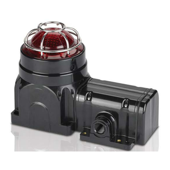
Model G-LED LED Beacon
For Use in Hazardous Locations
Maintenance Instructions
Global Series
Installation and
Advertisement
Table of Contents

Related Manuals for Federal Signal Corporation Global Series


Summary of Contents for Federal Signal Corporation Global Series
- Page 1 Global Series Model G-LED LED Beacon For Use in Hazardous Locations Installation and Maintenance Instructions To view this manual in Portuguese, go to www.federalsignal-indust.com. To view this manual in Mandarin, go to www.federalsignal-indust.com. To view this manual in Russian, go to www.federalsignal-indust.com.
- Page 2 Warranty – Seller warrants all goods for five years on parts and 2-1/2 years on labor, under the following conditions and exceptions: Seller warrants that all goods of Seller's manufacture will conform to any descriptions thereof for specifications which are expressly made a part of this sales contract and at the time of sale by Seller such goods shall be commercially free from defects in material or workmanship.
-
Page 3: Table Of Contents
Replacing the LED Array ..............23 Lubricating the Threaded Joints ............25 Ordering Replacement Parts and Accessories ......... 26 Getting Repair Service or Technical Assistance ....... 27 Returning the Product for Credit ............27 Model G-LED Global Series LED Beacon... - Page 4 Figure 13 Location of DIP switch for flash patterns ......21 Figure 14 Switch settings for flash patterns .......... 21 Figure 15 LED array and connector............24 © 2015 Federal Signal Corporation. All rights reserved. Model G-LED Global Series LED Beacon...
-
Page 5: Safety Messages To Installers And Users
Keep the unit tightly closed when in operation. • After installation, test the beacon system to ensure that it is operating properly. • After testing is complete, provide a copy of this instruction sheet to all personnel. Model G-LED Global Series LED Beacon... -
Page 6: Certification
The metallic brass inserts have a capacitance of 14 pF. The metallic guard has a capacitance of 18 pF. See the manufacturer’s instructions for further information. Model G-LED Global Series LED Beacon... -
Page 7: Unpacking The Beacon
Support at +1 708-534-4756 or +1 877-289-3246. Creating Combination Fixtures in the Field The Federal Signal Global Series Ex de products can be connected together in the field using interchangeable E-box end caps and a proprietary coupling system. The proprietary coupling system allows... -
Page 8: Mounting The G-Led Beacon
To adjust the vertical angle of the beacon, loosen the fasteners on the mounting bracket to disengage the ratchet. Vertically aim the beacon, and tighten the fasteners. Model G-LED Global Series LED Beacon... -
Page 9: Figure 2 Front View Of Trunnion-Mount Beacon
Installation and Maintenance Instructions Figure 2 Front view of trunnion-mount beacon 189.2 mm (7.45 in) 215.2 mm (8.47 in) Figure 3 Side view of trunnion mount 190.6 mm (7.50 in) Model G-LED Global Series LED Beacon... -
Page 10: Mounting The Surface-Mount Ex D Beacon
CAP SCREWS 105.9 mm (4.17 in 105.9 mm (4.17 in) Figure 6 Side view of Ex d beacon 190.6 mm (7.50 in) 132.6 mm (5.22 in) 34.9 mm 2X M20 GLAND ENTRIES (1.38 in) Model G-LED Global Series LED Beacon... -
Page 11: Mounting The Ex De Surface-Mount Beacon
Figure 7 Front view of Ex de surface mount 4X COUNTER-BORED HOLES TO FIT M8 SOCKET-HEAD CAP SCREWS 105.9 mm (4.17 in) 23.2 mm (0.91 in) 2X Ø8.5 mm 103.2 mm 3X M20 (4.06 in) GLAND ENTRIES 122.6 mm (4.83 in) Model G-LED Global Series LED Beacon... -
Page 12: Figure 8 Side View Of Ex De Surface Mount
Installation and Maintenance Instructions Figure 8 Side view of Ex de surface mount 227.4 mm (8.95 in) 272.0 mm (10.71 in) 3X M20 GLAND ENTRIES SEE ACCESSORIES FOR REPLACEABLE E-BOX END CAPS Model G-LED Global Series LED Beacon... -
Page 13: Safety Messages For Wiring
Because of space limitations, ensure the cable cores within the unit are not too slack. • In all countries, the wiring must comply with all national and local codes and standards. • Ensure that all nuts, bolts, and fixings are secure. Model G-LED Global Series LED Beacon... -
Page 14: Connecting To The Terminal Block
POLARITY MUST BE OBSERVED. In addition, damage will result if the voltage rating of the particular model is exceeded by more than 10 percent. This section has wiring instructions for the two flameproof models: • G-LED 24 Vdc • G-LED 120-240 Vac Model G-LED Global Series LED Beacon... -
Page 15: Wiring The Ex D Models
See Figure 10 on page 16. Connect the positive (+) power source wire to the terminal-block screw marked + . b. Connect the negative ( ) power source wire to the terminal ▬ block screw marked ▬ Model G-LED Global Series LED Beacon... -
Page 16: 120-240 Vac Models
To ensure O-ring compression, the cover must be fully seated against the housing when the threads are tightened. Turn the M3 set screw on the side of the housing until the screw contacts the housing. Model G-LED Global Series LED Beacon... -
Page 17: Preparing To Wire The Ex De Increased Safety Models
The G-LED terminal block is supplied with three poles and two conductors per pole. The terminal block allows for easy supply-in and loop-out wiring to connect beacons in series. Tools needed: • 3.0 mm hexagon key • No. 1 Phillips screwdriver • Wire stripper Model G-LED Global Series LED Beacon... -
Page 18: Wiring The Ex De Models
Connect the negative ( ) power source wire to the terminal ▬ block pole marked L2/- Figure 12 Connections for DC or AC Ex de beacons L1/+ L2/- L3/Alt+ Aud+ Aud- L1/+ L2/- L3/Alt+ Aud+ Aud- Model G-LED Global Series LED Beacon... -
Page 19: 120-240 Vac Models
Always allow the emitter to cool before handling it. The Model G-LED Series beacon has eight flash patterns that are selected by setting a DIP switch on the PCB. See Figures 13 and 14 on page 21. Model G-LED Global Series LED Beacon... - Page 20 Turn the M3 set screw against the housing until the screw contacts the housing. Reconnect power to the beacon. 10. Test the beacon by applying power and verifying the pattern. Model G-LED Global Series LED Beacon...
-
Page 21: Figure 13 Location Of Dip Switch For Flash Patterns
Strobe Simulation (60 FPM) 1 2 3 1 2 3 Random Blink Strobe Simulation (90 FPM) 1 2 3 1 2 3 Rotate (120 RPM) Severe Alert 1 2 3 1 2 3 Model G-LED Global Series LED Beacon... -
Page 22: Safety Messages To Maintenance Personnel
Ensure that the nameplate remains readable. • After performing any maintenance, test the beacon system to ensure that it is operating properly. Failure to follow all safety precautions and instructions may result in property damage, serious injury, or death. Model G-LED Global Series LED Beacon... -
Page 23: Maintaining The Beacon
Do not stare directly into the beacon at close range or permanent damage to your eyesight may occur. Federal Signal LED array part No. K859500823-* Model G-LED Global Series LED Beacon... -
Page 24: Figure 15 Led Array And Connector
Figure 15 LED array and connector J1 CONNECTOR LED ARRAY Remove the LED Array: Disconnect power to the beacon. Use the hexagon key to unscrew the set screw on the housing one full turn. Model G-LED Global Series LED Beacon... -
Page 25: Lubricating The Threaded Joints
M3 set screw on the side of the housing until the screw contacts the housing. Reconnect power to the beacon. Apply power and verify that the beacon operates properly. Lubricating the Threaded Joints A silicone based, non-hardening, chemically compatible grease can be applied if required. Model G-LED Global Series LED Beacon... -
Page 26: Ordering Replacement Parts And Accessories
Lens, Clear K859500815-02 Lens, Green K859500815-03 Lens, Red K859500815-04 Lens, Magenta K859500815-05 Lens, Yellow K859500815-06 LED Array, Amber K859500823-A LED Array, Blue K859500823-B LED Array, Green K859500823-G LED Array, Red K859500823-R LED Array, White K859500823-W Model G-LED Global Series LED Beacon... -
Page 27: Getting Repair Service Or Technical Assistance
Please contact your distributor for assistance. A product is qualified to be returned for credit when the following conditions are met: • The product is resalable and in the original cartons. • The product has not been previously installed. Model G-LED Global Series LED Beacon... - Page 28 Defective products that are returned within the warranty period will be repaired or replaced at Federal Signal’s sole discretion. Defective products do not include those products with lamp failure. Circumstances other than those listed above will be addressed on a case-by-case basis. Model G-LED Global Series LED Beacon...
-
Page 29: Table 3 Choosing Cable-Entry Devices For Equipment In Potentially Explosive Atmospheres
To G-LED-XXX-T-X maintain the ingress protection (Ex db trunnion of the beacon and terminal mount) enclosures the cable entry devices shall be IP6X certified. G-LED-XXX-E-X (Ex db e surface mount) Model G-LED Global Series LED Beacon...
Need help?
Do you have a question about the Global Series and is the answer not in the manual?
Questions and answers