Advertisement
Quick Links
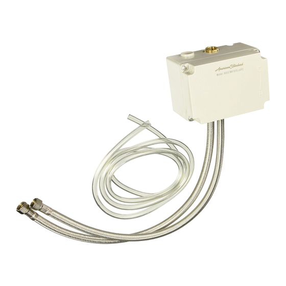
SELECTRONIC
Thermostatic Mixing Valve
605XTMV1070
Certified to comply with ASME A112.18.1M
© 2019 American Standard
M965327 REV. 1.2
NOTE TO INSTALLER: Please give this manual to the customer after installation.
NOTE TO INSTALLER: Please give this manual to the customer after installation.
To learn more about American Standard Selectronic
or e-mail us at: CRTTEAM@lixilamericas.com
For Parts, Service, Warranty or other Assistance,
please call (844) CRT-TEAM / (844) 278-8326
™
Specifications
Installation
Adjust Temperature
Service
Replacement Parts
®
Products visit our website at: www.americanstandard-us.com
(In Canada: 1-800-387-0369)
(In Toronto Area only: 1-905-306-1093)
1
2
3
3
4
Advertisement

Related Manuals for American Standard SELECTRONIC 605XTMV1070


Summary of Contents for American Standard SELECTRONIC 605XTMV1070
- Page 1 NOTE TO INSTALLER: Please give this manual to the customer after installation. NOTE TO INSTALLER: Please give this manual to the customer after installation. ® To learn more about American Standard Selectronic Products visit our website at: www.americanstandard-us.com or e-mail us at: CRTTEAM@lixilamericas.com...
- Page 2 © 2012 American Standard M965327 NOTE TO INSTALLER: Please give this manual to the customer after installation. To learn more about American Standard Faucets visit our website at: www.us.amstd.com or U.S. customer's e-mail us at: faucetsupport@amstd.com For Parts, Service, Warranty or other Assistance,...
- Page 3 INSTALLATION Fig. 3 LAVATORY RIM OR MOUNTING SURFACE MOUNT ENCLOSURE; Fig. 3 1. Remove the bottom SUPPLY HOSE (1) from the SELECTRONIC FAUCET CONTROL BOX (2). Fig. 3 Fig. 3a SUPPLIES 2. Remove BOTTOM PLUG (3) from SELECTRONIC FAUCET CONTROL BOX (2). Fig. 3 3.
- Page 4 Fig. 6 ADJUST TEMPERATURE TO ADJUST TEMPERATURE; Fig. 6 TO DECREASE TEMPERATURE 4mm HEX 1. Adjust temperature by inserting a 4mm Hex Wrench WRENCH into hex opening in the side of enclosure. Fig. 6. 2. To decrease temperature, rotate up. (clock-wise) TO INCREASE TEMPERATURE 3.
Need help?
Do you have a question about the SELECTRONIC 605XTMV1070 and is the answer not in the manual?
Questions and answers
How do you adjust the sensor eye, right now you have to put your hand right up to it to turn on ?