Advertisement
Quick Links
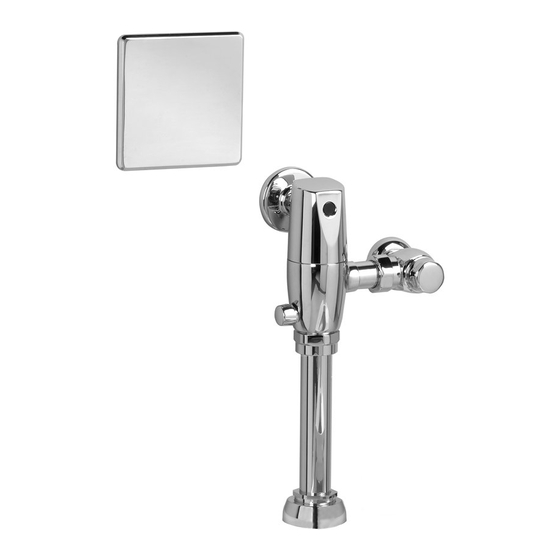
SELECTRONIC
AC POWERED PROXIMITY
EXPOSED TOILET FLUSH VALVE
1.1, 1.28, 1.6,
1.6/1.1 & 1.28/1.1 GPF
Certified to comply with ASME A112.19.2
© 2014 AS America, Inc.
M965644 REV. 1.1 (12/14)
NOTE TO INSTALLER: Please give this manual to the customer after installation.
NOTE TO INSTALLER: Please give this manual to the customer after installation.
To learn more about American Standard Selectronic
or e-mail us at: CRTTEAM@americanstandard.com
For Parts, Service, Warranty or other Assistance,
please call (844) CRT-TEAM / (844) 278-8326
®
6067 .111
6068.111
Exposed Flushometer
for 1-1/2" Top Spud Bowls
CLOG RESISTANT
• Self-cleaning piston valve prevents clogging and reduces maintenance.
ONE SENSOR FITS ALL
• Only 1 sensor for entire Selectronic™ line of faucets, urinals, and ush valves.
• Range can be adjusted manually or with optional remote control.
CAUTION: Use only American Standard
supplied cable sets. Using non-AS supplied
cables, or cutting, splicing or modifying any
components will void the warranty.
Products visit our website at: www.americanstandard-us.com
®
(In Canada: 1-800-387-0369)
(In Toronto Area only: 1-905-306-1093)
MODEL NUMBERS
6067 .121
6067 .161
6068.121
6068.161
6067 .721
6067 .761
6068.721
6068.761
Advertisement

Subscribe to Our Youtube Channel
Related Manuals for American Standard SELECTRONIC 6067.111


Summary of Contents for American Standard SELECTRONIC 6067.111
- Page 1 M965644 REV. 1.1 (12/14) NOTE TO INSTALLER: Please give this manual to the customer after installation. NOTE TO INSTALLER: Please give this manual to the customer after installation. To learn more about American Standard Selectronic Products visit our website at: www.americanstandard-us.com ®...
- Page 2 Thank you for selecting American-Standard...the benchmark of fine quality for over 100 years. To ensure that your installation proceeds smoothly--please read these instructions carefully before you begin. All American Standard Products Are Water Tested At Our Factory. UNPACKING Some Residual Water May Remain In The Valve During Shipping.
-
Page 3: Prior To Installation
Fig. 1 GENERAL DESCRIPTION: CAUTION: Use only American Standard Roughing-in Dimensions supplied cable sets. Using non-AS supplied SELECTRONIC™ cables, or cutting, splicing or modifying any PROXIMITY TOILET components will void the warranty. Right or Left Hand Installation FLUSH VALVE (Section 5) - Page 4 FLUSH VALVE INSTALLATION Fig.3 FINISHED WALL INSTALL SWEAT ADAPTER; Fig. 3 CENTER LINE OF FIXTURE SPUD CAUTION Turn water supplies off before beginning Note: Install Optional Sweat Adapter (Supplied) for copper pipe supply line. (A-B)= 32mm 1. Measure the distance (A) from the finished wall to the (1-1/4") FILE EDGES center of the inlet spud on the fixture.
- Page 5 FLUSH OUT SUPPLY LINES; Fig. 6 Fig. 6 1. Remove STOP VALVE COVER (1) from STOP VALVE (2). REMOVE COVER 2. Open STOP VALVE (2) with a flat blade screwdriver. 3. Turn on water supply to flush line of any debris or sediment.
-
Page 6: Electrical Installation
PLATE (6) into the two Slots located on the top edge of the COVER PLATE FRAME (5). Push on bottom until it snaps into place. Fig. 10a. CAUTION: Use only American Standard TABS supplied cable sets. Using non-AS supplied cables, or cutting, splicing or modifying any components will void the warranty. - Page 7 4. Place Y-ADAPTERS (2) into respective electrical box. 5. Reconnect the first unit’s Y-ADAPTER (2a) to power supply once all daisy-chain unit connections have been made. CAUTION: Use only American Standard supplied cable sets. Using non-AS supplied cables, or cutting, splicing or modifying any components will void the warranty.
-
Page 8: Maintenance
INSTALL CONDUIT, ESCUTCHEON Fig. 11 AND SENSOR CABLE; Fig. 11 1. Remove COVER (1). See step #5 to remove the COVER (1). 2. Thread CONDUIT (2) into COVER (1) and secure by tightening LOCK NUT (3). 3. Slide ESCUTCHEON (4) onto CONDUIT (2). Fig. 11. 4. - Page 9 SET DETECTION RANGE Fig. 13 (If Required) ; Fig. 13 & 14 Note: The detection distance is preset and ideal for most installations. Should an adjustment be required, follow the steps below. 1. To remove the COVER PLATE (1), insert WIRE KEY (2) (supplied) into the two holes located at the bottom of the COVER PLATE (1).
-
Page 10: Troubleshooting Flowcharts
Produc t nam e s l i sted herei n are tra dem ar ks of AS A m er i ca, I nc. ©2014 AGAIN TO PRIME THE VALVE. DOES FLUSHING STOP? To learn more about American Standard Selectronic® Products visit our website at: www.americanstandard-us.com or e-mail us at: CRTTEAM@americanstandard.com N N O O... - Page 11 Weekdays 8:00 a.m. to 7:00 p.m. EST Product names listed herein are trademar ks of AS Amer ica, In c. ©2 014 To learn more about American Standard Selectronic® Products visit our website at: www.americanstandard-us.com or e-mail us at: CRTTEAM@americanstandard.com...
Need help?
Do you have a question about the SELECTRONIC 6067.111 and is the answer not in the manual?
Questions and answers