Advertisement
SELECTRONIC
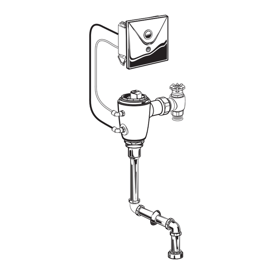
PROXIMITY CONCEALED
URINAL FLUSH VALVE
1.0, 0.5 & 0.125 GPF
Certified to comply with ASME A112.19.2
© 2014 AS America, Inc.
M965641 (11/14)
NOTE TO INSTALLER: Please give this manual to the customer after installation.
NOTE TO INSTALLER: Please give this manual to the customer after installation.
To learn more about American Standard Selectronic
or e-mail us at: CRTTEAM@americanstandard.com
For Parts, Service, Warranty or other Assistance,
please call (844) CRT-TEAM / (844) 278-8326
®
Top Spud
Concealed Flushometer
for 3/4" Top or Back Spud Urinals
CLOG RESISTANT
• Self-cleaning piston valve prevents clogging and reduces maintenance.
ONE SENSOR FITS ALL
• Only 1 sensor for entire Selectronic™ line of faucets, urinals, and
ush valves.
• Range can be adjusted manually or with optional remote control.
• Sensor Features Low Battery Indicator.
CAUTION: Use only American Standard supplied cable
sets. Using non-AS supplied cables, or cutting, splicing or
modifying any components will void the warranty.
Products visit our website at: www.americanstandard-us.com
®
(In Canada: 1-800-387-0369)
(In Toronto Area only: 1-905-306-1093)
MODEL NUMBERS 1.0, 0.5 & 0.125GPF
6061.X10
6061.X05
6062.X10
6062.X05
6063.X10
6063.X05
Concealed Back Spud
6061.X01
6062.X01
6063.X01
Advertisement
Table of Contents

Related Manuals for American Standard SELECTRONIC 6061.X10


Summary of Contents for American Standard SELECTRONIC 6061.X10
- Page 1 • Range can be adjusted manually or with optional remote control. • Sensor Features Low Battery Indicator. CAUTION: Use only American Standard supplied cable sets. Using non-AS supplied cables, or cutting, splicing or Certified to comply with ASME A112.19.2 modifying any components will void the warranty.
- Page 2 UNPACKING All American Standard Products Are Water Tested At Our Factory. Some Residual Water May Remain In The Valve During Shipping. Remove the Flush Valve items from the carton. The illustration below shows all items after they have been removed from the carton.
-
Page 3: General Description
Concealed Flushometer 25mm above fixture. Consult Codes for details. (1) MAX. for 3/4" Spud Fixtures CAUTION: Use only American Standard supplied cable sets. Using non-AS supplied cables, or cutting, splicing or 160mm Exclusive, self cleaning piston-type flush 127mm X 127mm... - Page 4 FLUSH VALVE INSTALLATION Fig.3 (TOP SPUD FIXTURE ILLUSTRATED) INSTALL ELECTRICAL BOX; Fig. 3 127mm 127mm 1. Cut a 127x127mm (5"x 5") opening in finished wall for ELECTRICAL BOX (1) at the dimension shown. 2. Rotate the 4 MOUNTING TABS (2) flat against the electrical box.
- Page 5 4 INSTALL VACUUM BREAKER AND Fig. 6 FLUSH CONNECTIONS; Fig. 6 1. Place the SPUD FLANGE (1) over the spud on the 3/4" TOP SPUD Fixture. Fig. 6. 2. Place FRICTION WASHER (3) and SEAL WASHER (4) inside SPUD COUPLING NUT (2) and thread onto Spud. Do not tighten fully.
- Page 6 INSTALL FLUSH VALVE; Fig. 7 Fig. 7 1. Insert the side ADJUSTABLE TAILPIECE (1) on the FLUSH VALVE (2) into the STOP VALVE (3). Lubricate the TAILPIECE O-RING (4) with water if necessary. Thread the COUPLING NUT (5) onto the STOP VALVE (3) and tighten lightly.
-
Page 7: Electrical Installation
ELECTRICAL INSTALLATION Fig. 9 T O P DC VERSION; Fig. 9, 10 1. Attach the SAFETY CHAIN (1) from the COVER PLATE (2) to the MOUNTING POST (3) as shown. Fig. 9. 2. Connect one end of the 27" EXTENSION CABLE (1) to one SENSOR CABLE (2). - Page 8 5. Place Y-ADAPTERS (3) into respective electrical box. 6. Plug in AC power supply into wall outlet once all daisy-chain unit connections have been made. CAUTION: Use only American Standard supplied cable sets. Using non-AS supplied cables, or cutting, splicing or modifying any components will void the warranty.
- Page 9 INSTALL COVER PLATE; Fig. 12 Fig. 12 1. Install the two TABS (1) on the back side of COVER PLATE (2) into the two SLOTS (3) located on the top edge of the ELECTRICAL BOX (4). 2. Push on the bottom edge of the COVER PLATE (2) until it snaps into place.
-
Page 10: Maintenance
MAINTENANCE Fig. 14 INSTALL NEW BATTERY; Fig. 14 1. Remove the COVER PLATE (1). For removing front panel instructions, see Step 10. 2. Remove old BATTERY (2) from BATTERY HOLDER (4). Install the new BATTERY (3), making sure the shape of the BATTERY (3) follows the shape of the BATTERY HOLDER (4). -
Page 11: Care Instructions
SET DETECTION RANGE Fig. 16 (If Required); Fig. 16 & 17. Note: The detection distance is preset and ideal for most installations. Should an adjustment be required, follow the steps below. 1. Remove COVER PLATE (1). See Step 10 for front panel removal instructions. -
Page 12: Troubleshooting Flowcharts
P ro d u c t n a m e s l is te d h e r ei n a r e tr a d em a r ks o f A S A me ri c a , I n c. © 2 0 1 4 AGAIN TO PRIME THE VALVE. To learn more about American Standard Selectronic® Products visit our website at: DOES FLUSHING STOP? www.americanstandard-us.com or e-mail us at: CRTTEAM@americanstandard.com...
Need help?
Do you have a question about the SELECTRONIC 6061.X10 and is the answer not in the manual?
Questions and answers