Advertisement
SELECTRONIC™
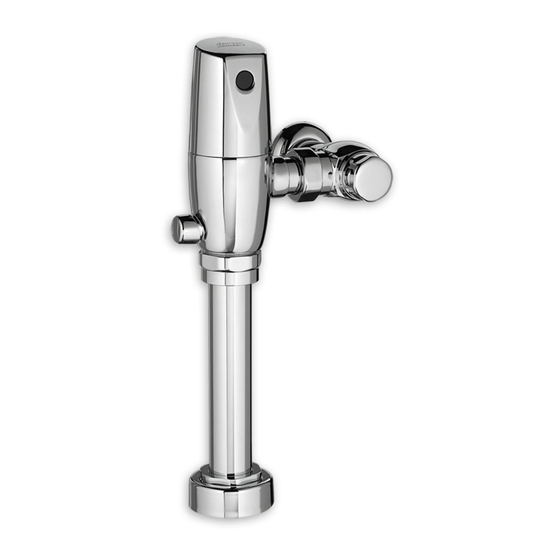
PROXIMITY URINAL FLUSH VALVE
0.125 GPF & (0.5 LPF)
Certified to comply with ASME A112.19.2M
© 2009 AS America, Inc.
M968541 REV.1.2
NOTE TO INSTALLER: Please give this manual to the customer after installation.
To learn more about American Standard Faucets visit our website at: www.americanstandard-us.com
or U.S. customer's e-mail us at: faucetsupport@americanstandard.com
For Parts, Service, Warranty or other Assistance,
1-800-442-1902 (In Canada: 1-800-387-0369)
please call
Exposed Flushometer
for 3/4" Top Spud Urinals
CLOG RESISTANT
• Self-cleaning piston valve prevents clogging and reduces maintenance.
ONE SENSOR FITS ALL
• Only 1 sensor for entire Selectronic™ line of faucets, urinals, and flush valves.
• Range can be adjusted manually or with optional remote control.
• Sensor Features Low Battery Indicator.
(In Toronto Area only: 1-905-3061093)
(In Toronto Area only: 1-905-3061093)
MODEL NUMBERS
6063.013
6590.525
Advertisement
Table of Contents

Subscribe to Our Youtube Channel
Related Manuals for American Standard SELECTRONIC 6590.525


Summary of Contents for American Standard SELECTRONIC 6590.525
- Page 1 M968541 REV.1.2 NOTE TO INSTALLER: Please give this manual to the customer after installation. To learn more about American Standard Faucets visit our website at: www.americanstandard-us.com or U.S. customer's e-mail us at: faucetsupport@americanstandard.com For Parts, Service, Warranty or other Assistance,...
-
Page 2: Care Instructions
M968541 REV.1.1 NOTE TO INSTALLER: Please give this manual to the customer after installation. To learn more about American Standard Faucets visit our website at: www.americanstandard-us.com or U.S. customer's e-mail us at: faucetsupport@americanstandard.com For Parts, Service, Warranty or other Assistance,... -
Page 3: General Description
Fig. 1 GENERAL DESCRIPTION: Roughing-in Dimensions SELECTRONIC™ PROXIMITY URINAL FLUSH VALVE DETECTION ZONE 400mm-800mm Exposed Flushometer (15-3/4 TO 31-1/2) for 3/4" Top Spud Fixtures 72mm FINISHED WALL (2-7/8) Exclusive, self cleaning piston-type flush 57mm valve with proximity operation and (2-1/4 MIN.) manual override. - Page 4 INSTALL SWEAT SOLDER Fig.3 Fig.3a ADAPTER; Fig. 3 FINISHED WALL CENTER LINE OF Turn water supplies off CAUTION FIXTURE SPUD before beginning Note: Install Optional Sweat Solder Adapter (Supplied) for copper pipe supply line. Fig. 3. (A-B)= 1. Measure the distance (A) from the finished wall to the 32mm center of the inlet spud on the fixture.
- Page 5 FLUSH OUT SUPPLY LINES; Fig. 6 Fig. 6 1. Remove COVER (1) from SUPPLY STOP (2). REMOVE COVER 2. With a flat blade screwdriver open SUPPLY STOP (2). 3. Turn on water supply to flush line of any debris or sediment.
- Page 6 INSTALL FLUSH VALVE; Fig. 8a Fig. 8a & 8b 1. As shown in Fig. 8a, insert the side INLET FLANGE (1) on the FLUSH VALVE (2) into the SUPPLY STOP (3). Lubricate the INLET FLANGE O-RING (4) with water if necessary.
- Page 7 If these items do need replacement they must be purchased separately or order the complete flush valve assembly from American Standard. 1. Remove COVER (1) from SUPPLY STOP (2) if installed. Fig. 10.
- Page 8 HOW TO SET DETECTION RANGE HOW TO SET DETECTION RANGE Fig. 13 (If Required) ; Fig. 13 (If Required) ; Fig. 13 & 14 Note: The detection distance is preset and is ideal for most installations. Should an adjustment be required Fig.
- Page 9 M968541 REV.1.2...
-
Page 10: Model Numbers
SELECTRONIC™ PROXIMITY URINAL FLUSH VALVE 0.125 GPF & (0.5 LPF) MODEL NUMBERS 6063.013 M962665-0020130A COVER ASSEMBLY FOR FLUSH VALVE WITH 0.125 gpf 6590.525 (BATTERY INCLUDED) A923654-0070A BATTERY 6VCR-P2 A950223-0070130A SENSOR ASSEMBLY W/MTG. KIT. A906680-0070A (0.125 gpf) BONNET NUT M962664-0070A SOLENOID ASSEMBLY OPTIONAL ADJUSTABLE TAILPIECE (Purchased Separtely) M962836-0020A (8-1/2 to 9-1/4 Rough-in)
Need help?
Do you have a question about the SELECTRONIC 6590.525 and is the answer not in the manual?
Questions and answers