WEIGL ProCommander Series Wiring Diagrams
Hide thumbs
Also See for ProCommander Series:
- Wiring diagram (12 pages) ,
- Menu plan (9 pages) ,
- Instruction manual (102 pages)

Related Manuals for WEIGL ProCommander Series


Summary of Contents for WEIGL ProCommander Series
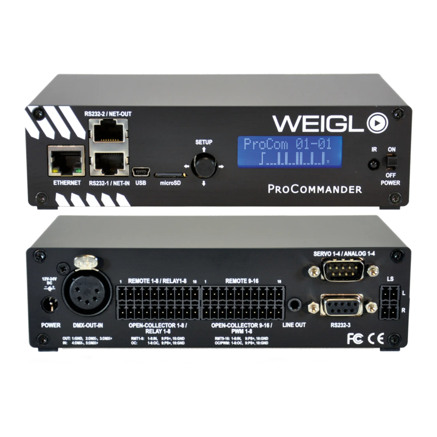
- Page 2 FRONT WIRING DIAGRAM FOR ProCommander Series FRONT WIRING DIAGRAM FOR ProCommander 2 Device address 3 (!ssi3#) CAT5 Device address 2 (!ssi2#) CAT5 Device address 1 (!ssi1#) Daisy-Chain Connection for Pro-I/O NETWORK Press button to store permanently changes in menu USB for Control and Configuration...
- Page 3 EXTERNAL POWER SUPPLY REAR WIRING DIAGRAM FOR ProCommander 2 INPUT CIRCUIT IN9-IN16 ANALOG OUT 1, max. 15mA 0-10V ANALOG OUT 2, max. 15mA INPUT CIRCUIT IN1-IN8 0-10V ANALOG IN 1 ANALOG IN 8 (0-10V) (0-10V) ANALOG OUT 3, max 15mA 0-10V ANALOG OUT 4, max 15mA 0-10V...
- Page 4 EXTERNAL POWER SUPPLY WIRING DIAGRAM FOR ProCommander 2 and ProCommander PHX RELAY OPTION INPUT CIRCUIT IN9-IN16 ANALOG OUT 1, max. 15mA 0-10V ANALOG OUT 2, max. 15mA 0-10V ANALOG IN 1 ANALOG IN 8 (0-10V) (0-10V) ANALOG OUT 3, max 15mA 0-10V ANALOG OUT 4, max 15mA Connection of internal relays...
- Page 5 REAR WIRING DIAGRAM FOR ProCommander PHX INPUT CIRCUIT IN9-IN16 INPUT CIRCUIT IN1-IN8 ANALOG IN 1 ANALOG IN 8 20W AMPLIFIER (0-10V) (0-10V) DMX512-IN LEFT 4/8 Ohm LEFT 4/8 Ohm PS+: 12V-24V PS: GND RIGHT 4/8 Ohm EXTERNAL POWER SUPPLY + EXTERNAL POWER SUPPLY GND RIGHT 4/8 Ohm...
- Page 6 INTERNAL AUDIO ROUTING ProCommander PHX à Audio mixer AUDIO DECODER 1 20W AMPLIFIER with Audio mixer LEFT Audio data from card for channel 1 RIGHT 20W AMPLIFIER Virtuel switches: can be controlled by PHX routing command !phx0# !phx0# !phx1# !phx2# !phx0# !phx2# !phx1#...
- Page 7 ProCommander ES network wiring during programming and Device address 3 playback from card (!ssi3#) CAT5 Device address 2 (!ssi2#) NETWORK CAT5 Device address 1 (!ssi1#) ProCommander ES network wiring during playback from Device address 3 card (!ssi3#) CAT5 Device address 2 (!ssi2#) CAT5 Device address 1...
- Page 8 INPUT CIRCUIT IN1-IN8 REAR WIRING DIAGRAM FOR ProCommander ES 16 Key Matrix Connection Firmware version >= 1.25 required! Parallel Wiring Matrix Wiring Activate matrix function: !skm1# Deactivate matrix function: !skm0# Will be stored in EEProm, therefore function is the same after power cycle. LEFT 4/8 Ohm DMX512-UNIVERSE...
- Page 9 REAR WIRING DIAGRAM FOR ProCommander LX ANALOG OUT 1, max. 15mA INPUT CIRCUIT IN9-IN16 0–10 V ANALOG OUT 2, max. 15mA 0–10 V INPUT CIRCUIT IN1-IN8 ANALOG IN 1 ANALOG IN 8 (0-10V) (0-10V) ANALOG OUT 3, max. 15mA 0–10 V DMX512-IN ANALOG OUT 4, max.
- Page 10 WIRING DIAGRAM FOR ProCommander LX RELAY OPTION ANALOG OUT 1, max. 15mA INPUT CIRCUIT IN9-IN16 0–10 V ANALOG OUT 2, max. 15mA 0–10 V INPUT CIRCUIT IN1-IN8 ANALOG IN 1 ANALOG IN 8 (0-10V) ANALOG OUT 3, max. 15mA (0-10V) 0–10 V DMX512-IN ANALOG OUT 4, max.
- Page 11 REAR WIRING DIAGRAM FOR ProCommander LTC EXTERNAL POWER SUPPLY + Pin 5.1 and Pin 5.2 internally connected! LOAD 1 LOAD 4 Pin 6.1 and Pin 6.2 internally connected! EXTERNAL POWER SUPPLY GND RS232 RS232 Audio Out RIGHT INPUT CIRCUIT 1-8 Audio Out LEFT PS+: 12V PS: GND...
- Page 12 Weigl-EM is the headquarter and hardware manufacturer Weigl Works, LLC | 440-941-5849 | www.WeiglWorks.com | Info@WeiglWorks.com Weigl Works, LLC is the exclusive North American distributor of Weigl-EM products ©2014 - Weigl-EM & Weigl Works, LLC Information deemed accurate, but not guaranteed. Subject to change without notice.
Need help?
Do you have a question about the ProCommander Series and is the answer not in the manual?
Questions and answers