
Related Manuals for YOKOGAWA UTAdvanced UP55A


Summary of Contents for YOKOGAWA UTAdvanced UP55A
- Page 1 UTAdvanced UP55A Program Controller Parameter Maps and Lists TI 05P02C41-01EN ©Copyright July. 2011 1st Edition July. 2011 Page 1 / 25...
- Page 2 UTAdvanced UP55A Introduction Brief Description of Sheets This sheet provides a brief description of the following sheets entitled "Names and Functions of Display Parts," "Operation and Program Parameter Map," "Setup Parameter Map," "List of Parameters," "Program Data Sheet," and "Example."...
-
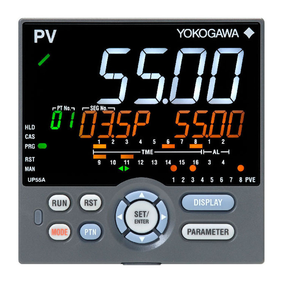
Page 3: Names And Functions Of Display Parts
UTAdvanced UP55A Names and Functions of Display Parts UP55A Display Parts Name Description No. in figure Displays PV. Displays an error code if an error occurs. PV display Displays the scrolling guide in the Menu Display and Parameter Setting Display when the (white or red) guide display ON/OFF is set to ON. - Page 4 UP55A Key Parts Name Description No. in figure Used to switch the Operation Displays. Press the key in the Operation Display to switch the provided Operation Displays. DISPLAY key Press the key in the Menu Display or Parameter Setting Display to return to the Operation Display.
- Page 5 Brief Description of Parameter Map The parameter display level is a function to control the parameters to be displayed. The factory setting is LEVL=STD. The control prevents unintentional change of the function. The parameter display level is just a function to hide the display so the set function works. Changing of parameter display level The parameters to be displayed can be controlled by changing the setting value for setup parameter LEVL.
- Page 6 The following operating procedure describes an example of setting alarm setpoint (A1) 1. Hold down the PARAMETER key for 3 seconds in the Operation Display to call up the [MODE] Menu Display. 2. Press the Right arrow key to display the [AL] Menu Display. 3.
- Page 7 How to Set Parameter Setpoint Numeric Value Setting Selection Data Setting Time (minute.second) Setting Page 7 / 25...
-
Page 8: List Of Display Symbols
List of Display Symbols The following shows the parameter symbols, menu symbols, alphanumeric of guide, and symbols which are displayed on the UP55A. Figure (common to all display area) PV display (14 segments): Alphabet Symbol display and Data display (11 segments): Alphabet Group display (7 segments): Alphabet PV display (14 segments): Symbol Page 8 / 25... - Page 9 UTAdvanced UP55A Operation and Program Parameter Map * This parameter map is for the case that the control mode (CTLM) is set to single loop control (SGL). Some parameters are not displayed according to model and suffix codes. For details, refer to the User's Manual.
-
Page 10: Setup Parameter Map
UTAdvanced UP55A Setup Parameter Map * This parameter map is for the case that the control mode (CTLM) is set to single loop control (SGL). Some parameters are not displayed according to model and suffix codes. For details, refer to the User's Manual. - Page 11 UTAdvanced UP55A List of Parameters * This parameter lists are for the case that the control mode (CTLM) is set to single loop control (SGL). Some parameters are not displayed according to model and suffix codes. For details, refer to the User's Manual.
- Page 12 Program pattern-2 Program Pattern Setting retransmission (PT2.G=ON) Menu Symbol Name Display level Setting range Initial value User setting User setting PROG> 0.0 to 100.0% of PV input range (EU) Final target setpoint EASY P.RL Sheet"Program Sheet"Program PTNO. (Setting range: P.RL to P.RH) Data Sheet"...
- Page 13 SP-related Setting Menu Symbol Name Display level Setting range Initial value User setting RSP: Via remote (aux. analog) input Remote input method COM: Via communication Remote input filter OFF, 1 to 120 s Remote input ratio 0.001 to 9.999 1.000 0.0 % of PV input range Remote input bias -100.0 to 100.0% of PV input range span (EUS)
- Page 14 Group 1 Group 2 Group 3 Group 4 Group 5 Group 6 Group 7 Group 8 PID Setting (S.PID=1) (S.PID=2) (S.PID=3) (S.PID=4) (S.PID=5) (S.PID=6) (S.PID=7) (S.PID=8) Menu Symbol Name Display level Setting range Initial value User setting User setting User setting User setting User setting User setting...
- Page 15 10-segment Linearizer-1 Setting Menu Symbol Name Display level Setting range Initial value User setting OFF: Disable PV: PV analog input RSP: RSP analog input AIN2: AIN2 analog input PYS1 10-segment linearizer-1 selection AIN4: AIN4 analog input (CTLM: SGL) PVIN: PV input OUT: OUT analog output OUT2: OUT2 analog output RET: RET analog output...
-
Page 16: Setup Parameters
Setup Parameters Control Function Setting Menu Symbol Name Display level Setting range Initial value User setting SGL: Single-loop control CAS1: Cascade primary-loop control CAS: Cascade control CTLM Control mode PVSW: Loop control with PV switching PVSEL: Loop control with PV autoselector * When using the ladder program, the control mode cannot be changed. - Page 17 AIN2 Aux. Analog Input Setting Menu Symbol Name Display level Setting range Initial value User setting 0.4-2V: 0.400 to 2.000 V 1-5V: 1.000 to 5.000 V AIN2 AIN2 aux. analog input type EASY 0-2V: 0.000 to 2.000 V 1-5V 0-10V: 0.00 to 10.00 V 0-125: 0.000 to 1.250 V -: No unit C: Degree Celsius...
- Page 18 Output Setting Menu Symbol Name Display level Setting range Initial value User setting Control output or Heating-side control output (Lower two digits) 00: OFF 01: OUT terminals (voltage pulse) 02: OUT terminals (current) 03: OUT terminals (relay/triac) 04: OUT2 terminals (voltage pulse) 05: OUT2 terminals (current) 06: OUT2 terminals (relay/triac) Standard type: 00.03...
- Page 19 Ethernet Communication Setting Menu Symbol Name Display level Setting range Initial value User setting ETHR High-speed response mode EASY OFF, 1 to 8 9600: 9600 bps Baud rate EASY 19200: 19.2k bps 38400 38400: 38.4k bps NONE: None Parity EASY EVEN: Even EVEN ODD: Odd...
- Page 20 Display Function Setting Menu Symbol Name Display level Setting range Initial value User setting 0: Fixed in white 1: Fixed in red 2: Link to alarm 1 (Alarm OFF: white, Alarm ON: red) 3: Link to alarm 1 (Alarm OFF: red, Alarm ON: white) 4: Link to alarm 1 or 2 (Alarm OFF: white, Alarm ON: red) DISP PCMD...
- Page 21 SELECT Display Setting Menu Symbol Name Display level Setting range Initial value User setting CSEL SELECT Display-1 registration OFF, 2201 to 5000 SELECT Display-2 registration For the D register number, see the UTAdvanced Series Communication Interface User’s Manual SELECT Display-3 registration Main registration parameters SELECT Display-4 registration - Group 1 (S.PID=1)
- Page 22 DI Function Numbering Menu Symbol Name Display level Setting range Initial value User setting DI.NU PT.B0 Bit-0 of Program pattern number EASY 5089 Set an I relay number of contact input. PT.B1 Bit-1 of Program pattern number EASY 5090 Set “OFF” to disable the function. PT.B2 Bit-2 of Program pattern number EASY...
- Page 23 Error and Version Confirmation Menu Symbol Name Display level Setting range PA.ER Parameter error status EASY OP.ER Option error status EASY AD1.E A/D converter error status 1 EASY AD2.E A/D converter error status 2 EASY PV1.E Loop-1 PV input error status EASY PV2.E Loop-2 PV input error status...
- Page 24 UTAdvanced UP55A Program Pattern Setup Charts CAUTION Note that the program patterns are all deleted if the settings change after creating program patterns. Be sure to check the PV input range, Program time unit (TMU), and Segment setting method (SEG.T) before creating.
- Page 25 UTAdvanced UP55A Program Pattern Setup Charts CAUTION Note that the program patterns are all deleted if the settings change after creating program patterns. Be sure to check the PV input range, Program time unit (TMU), and Segment setting method (SEG.T) before creating.
Need help?
Do you have a question about the UTAdvanced UP55A and is the answer not in the manual?
Questions and answers