YOKOGAWA UP150 Instruction Manual
Hide thumbs
Also See for UP150:
- User manual (37 pages) ,
- Instruction manual (14 pages) ,
- User manual (9 pages)

Related Manuals for YOKOGAWA UP150


Summary of Contents for YOKOGAWA UP150
- Page 1 Instruction UP150 Manual Program Controller IM 5E1E70-01E IM 5E1E70-01E 1st Edition...
-
Page 2: Table Of Contents
Please read through this instruction manual to ensure correct usage of the controller and keep it handy for quick reference. CONTENTS Notice ........................... What is on the Front Panel? ..................Installing the Controller .................... Panel Cutout Dimensions and External Dimensions..........Wiring .......................... - Page 3 Checking Package Contents Before using the product, check that its model & suffix codes are as you ordered. Model and Suffix Codes Suffix code Description Model UP150 Program controller –V Control output for general- Voltage pulse output (time-proportional PID) –A...
-
Page 4: Notice
NOTICE The following safety symbol is used both on the product and in this instruction manual. This symbol stands for “Handle with Care.” When displayed on the product, the operator should refer to the corresponding explanation given in the instruction manual in order to avoid injury or death of personnel and/or damage to the product. -
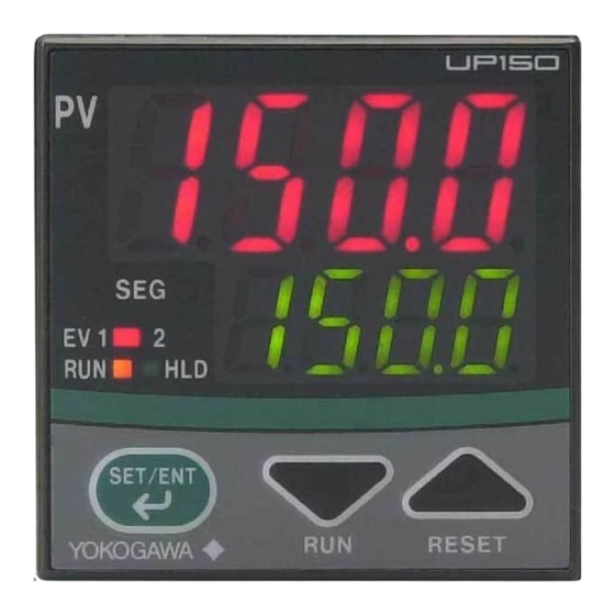
Page 5: What Is On The Front Panel
WHAT IS ON THE FRONT PANEL? Name Function PV display (red) Indicates PV (measured value) and character information such as parameter codes and error codes. Indicates PV and “AT” alternately during Auto-tuning. SP display (green) Indicates SP (target setpoint) and parameter values. SEG lamp (green) Lit when the value of “Segment No.”... -
Page 6: Installing The Controller
Do not mount it facing downward. 30° (MAX) Mounting the Controller Panel 2. Push the bracket to the panel, and then secure the bracket 1. Affix the bracket over the back into position. end of the controller. UP150 Bracket IM 5E1E70-01E... -
Page 7: Panel Cutout Dimensions And External Dimensions
PANEL CUTOUT DIMENSIONS AND EXTERNAL DIMENSIONS 1. General Mounting 2. Side-by-side Close Mounting (Splash-proof construction is unavailable) Unit: mm min. 70 × +0.6 [(N –1) N is the number of controllers. If N > 5, then measure the actual length. +0.6 Panel thickness 1 to 10... -
Page 8: Wiring
NOTE • Always fix a terminal cover bracket to the UP150 controller before wiring if an optional anti-electric- shock terminal cover (part number: L4000FB) is used. Cable Specifications and Recommended Products Power supply and relay contact output 600V vinyl insulated wire/cable, JIS C3307, 0.9 to 2.0mm... - Page 9 UP150 Terminal Arrangement Universal input-selectable Event Outputs Measured Value Input input type RTD Input TC Input – Power Supply Control Output 4 to 20 mA Output Voltage Pulse Output RS-485 Digital Input HOLD RSB(+) – – RSA(–) Specify one for the output signal type.
-
Page 10: Hardware Specifications
EN55011: Class A, Group 1 for EMI (emission) EN55082-2: 1995 for EMS (immunity) The UP150 program controllers conform to the standards specified under the following conditions. • All wires except those for the power supply and relay contact output terminals are shielded. -
Page 11: Key Operations
KEY OPERATIONS NOTE At power-on, the controller displays the operation display , but if the input range setting remains OFF, then “IN” appears. In this case, press the key to display the input range code you want to use, then press the key to register it. - Page 12 On/off. • When UP150 is in Program operation, the HOLD appears in the display. • When UP150 is not in Program The period flashes. operation, the CTL appears. If then, go to Step 4. Step 6:...
- Page 13 Flowchart Power ON When input range code has been already set, the operation display 1 shown below appears. is displayed Press the key to move between items Operation display Measured input value (PV) Target setpoint (SP) is displayed Target setpoint (SP) at operation display Operation display Segment No.
- Page 14 NOTE When “In” appears, press the key to display the input range code you want to use, then press key to register it. After this operation, the controller shows the operation display 1 . Note Press the key for at least 3 seconds. (To operation display 1 ) Program parameter setting display...
- Page 15 This page left intentionally blank. IM 5E1E70-01E...
- Page 16 Parameter Lists (1) Target Setpoint (SP) and Timer Setting 1 and 2 Code Name Setting range and unit Default User setting (SP value display) Target “Target setpoint”, “Segment No. at present” and setpoint “Remaining segment time” are not parameters to be set. You can confirm the value of these.
- Page 17 (3) Setup Parameters Code Name Setting range and unit Default User setting Input type 1 to 47 (See input range code list.) OFF: No input SUPER ON: Uses the SUPER function function OFF: Does not use SUPER function Note: Not displayed when on/off control Direct/reverse 0: Reverse action action...
- Page 18 (4) Program Parameters Code Name Setting range and unit Default User setting Event 1 type 0: PV event 1: Time event PV event 1 OFF or 1 to 10 (see the table of PV event function list) type PV event 1 •...
- Page 19 PV Event (alarm) Function List PV event PV event Action Action type code type code “Opn” and “Cls” indicate that “Opn” and “Cls” indicate that PV event PV event the relay contact is opened the relay contact is opened Closed Open Closed Open...
- Page 20 Time Event The time event feature begins countdown when a program starts running, and after the elapse of a preset time, output an on-time event (contact output ON) or off-time event (contact output OFF). The time of time event is not elapsed during “Hold” or “Wait” status. When the “Advance” is executed, remaining time in the segment is canceled.
- Page 21 Description of Parameters This section describes the parameter functions specific to the UP150 program controller. (The functions described in other sections of this manual and the general functions are not discussed.) Parameter Function Parameter Function SUPER Control mode The SUPER function is effective in the following cases: UP150 has two control mode.
-
Page 22: Program Operating Function
Overview of Program Setting To operate the controller using a program, first create the program. The UP150 have one program pattern. Program operation is based on a program pattern consisting of up to 16 segments as shown in the figure below. To create a program pattern, set the target setpoint to be rached and segment time for each segment. - Page 23 Program Pattern Setting Table Use a copy of the program pattern setting table to develop the program. This will allow you to visualize the program. (Please copy the table and use it to develop your own programs.) Device name Start target setpoint value (SSP) Program No.
- Page 24 “Creating program” must be finished before starting Step 1: program operation. Press key to reset the program operation, and confirm Step 1: that the UP150 shows the Confirm that the controller shows operation display , or . the operation display , or . Confirm that “RUN”...
- Page 25 Conditions for Starting Program The PV value is given priority when the operation starts. The following is an example of PV startup with gradient- priority. If segment 2 is a soak-interval segment Program-driven operation starts from any of the points A (SSP) to C. For other information, see the following table.
- Page 26 If segment 3 is a soak-interval segment: The starting point of program-driven operation is any of points A (SSP) to E. A(SSP) Time Seg.1 Seg.2 Seg.3 Seg.4 Example Where Segment 3 is a Soak-Interval Segment A(SSP) Time Seg.1 Seg.2 Seg.3 Seg.4 Example With No Soak-Interval Segment The starting point of program-driven operation is determined by a where the measured input value (PV) is...
- Page 27 If the segment consists of an ascending gradient (ramp) only: The starting point of program-driven operation is any of points A (SSP) to E. Note (see below table) A(SSP) Time Seg.1 Seg.2 Example Where the Segment Consists of an Ascending Gradient (Ramp) Only The starting point of program-driven operation is determined by where the measured input value (PV) is located at the time the operation starts.
- Page 28 In the case of other program pattern is set. The starting point of program-driven operation is any of points A (SSP) to D. A(SSP) Time Seg.1 Seg.2 Seg.3 Seg.4 Seg.5 A(SSP) Time Seg.1 Seg.2 Seg.3 Seg.4 Seg.5 The starting point of program-driven operation is determined by where the measured input value (PV) is located at the time the operation starts.
- Page 29 Wait operation is available only at a segment junction that transfers from ramp to soak. SEGn–1 SEGn SEGn+1 Wait Zone WTZ Wait Zone WTZ The controller (UP150) can move to the next segment (SEGn+1) when the PV reaches wait zone. The time is not elapced Time event During the “wait”, the timer for the program pattern progress stops, so that time event (EVn) is held.
- Page 30 HOLD Function During program-driven operation, the time of “segment time” can be stopped by “HOLD function”. When the controller is in “Hold”, the time of time events are also stopped. (PV events do not stop at this time.) When program-driven operation is held, time event and segment time are extended only by amount of the hold. “Hold”...
- Page 31 Advance Function Advance (moving program pattern forward 1 segment) can be executed by key operation or via communication. If advance is executed at the final segment, the system operates according to the set junction code. If advance is executed during hold, hold is released. When advance is executed, time and event move forward. SEG1 SEG2 SEG3...
- Page 32 Junction Code The operation at the end of program pattern can be specified by junction code (JC). Reset termination (JC = 0) At program termination, the controller enters reset status. At this time, control output becomes the preset output (0%), and event status is reset. Hold termination (JC = 1) At program termination, the system enters hold status.
-
Page 33: Troubleshooting
TROUBLESHOOTING In the event of an abnormality, perform the following checks as outlined by the flowchart. Is the controller defective? Communication Completely inactive? Key operation failure? Display failure? I/O signal failure? failure? Check the terminal connection Check key-lock Turn the power off, Verify the I/O spec.
Need help?
Do you have a question about the UP150 and is the answer not in the manual?
Questions and answers