Sign In
Upload
Manuals
Brands
Spectrex Manuals
Security Sensors
SharpEye 40/40UFI
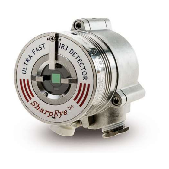
Spectrex SharpEye 40/40UFI Manuals
Manuals and User Guides for Spectrex SharpEye 40/40UFI. We have
1
Spectrex SharpEye 40/40UFI manual available for free PDF download: User Manual
Spectrex SharpEye 40/40UFI User Manual (84 pages)
Ultra-Fast IR3 Flame Detector
Brand:
Spectrex
| Category:
Security Sensors
| Size: 1 MB
Table of Contents
Table of Contents
5
List of Figures
9
1 About this Guide
11
Release History
12
Glossary and Abbreviations
12
Notifications
14
2 Product Overview
15
Approvals
15
Model and Types
16
Table 1: Wiring Options
17
Features and Benefits
18
Principles of Operation
18
Hydrocarbon Fire Detection
18
Heated Optics
19
HART Protocol
19
RS-485 Modbus
19
Product Certification
20
Performance Considerations
22
Detection Sensitivity
22
Table 2: Sensitivity Range Levels
22
Cone of Vision
23
Table 3: Fuel Sensitivity Ranges
23
False Alarm Prevention
24
Figure 1: Field of View
24
Table 4: Immunity to False Alarm Sources
24
Visual Indicators
25
Table 5: Welding Immunity Distance
25
Table 6: LED Indications
25
Output Signals
26
Figure 2: Indicator LED
26
Table 7: Available Output Types
26
Detector Status
27
Table 8: Detector Status
27
Table 9: Output Signals Versus Detector State
27
Auxiliary Relay as End-Of-Line
28
Internal Detector Tests
28
Continuous Feature Test
29
Response to Fault Indication
29
Built-In-Test (BIT)
29
Table 10: Results of a Successful BIT
30
Table 11: Results of an Unsuccessful BIT
30
3 Installing the Detector
31
General Guidelines
31
Sensitivity
31
Wiring
31
Spacing and Location
31
Environment
31
Aiming the Detector
31
Unpacking the Product
32
Checking the Product Type
32
Required Tools
32
Table 12: Tools
32
Certification Instructions
33
Special Instructions for Safe Use
33
General Instructions
34
Installation Cables
34
Conduit Installation
35
Installing the Tilt Mount
36
Figure 3: Detector with Tilt Mount
36
Figure 4: Tilt Mount Assembly
37
Figure 5: Tilt Mount Assembly (Dimensions in Millimeters and Inches)
37
Tilt Mount Assembly
37
Connecting the Detector
38
Verifying the Detector Wiring
39
Figure 6: Detector with Cover Removed
39
Table 13: Model 40/40UFI Wiring Options
40
Configuring Your Detector
41
Sensitivity
42
Alarm Delay
42
Table 14: Sensitivity Settings
42
Address Setup
43
Function Setup
43
Heated Optics
43
Table 15: Functions
43
4 Operating the Detector
45
Powering up
45
Safety Precautions
45
Default Functions Settings
46
Testing Procedures
46
Automatic BIT Test
46
Table 16: Default Function Values
46
Testing with Flame Simulator Model FS-1100
47
Table 17: Results of Successful Flame Simulator Test
47
5 Maintenance and Troubleshooting
49
Maintenance
49
General Procedures
49
Periodic Procedures
49
Keeping Maintenance Records
50
Troubleshooting
50
Table 18: Troubleshooting Table
50
Appendix A: Specifications
53
Technical Specifications
53
Electrical Specifications
54
Electrical Input Protection
54
Outputs
54
Electrical Interface
54
Table 19: Electrical Specifications
54
Electrical Outputs
55
Table 20: Contact Ratings
55
Table 21: 20Ma Current Output
55
Heated Optics
56
Approvals
57
Hazardous Area Approvals
57
Functional Approvals
57
Mechanical Specifications
58
Enclosure
58
Water and Dust Tight
58
Electronic Modules
58
Electrical Connection (2 Entries)
58
Dimensions
58
Weight
58
Environmental Specifications
58
High Temperature
58
Low Temperature
58
Humidity
59
Salt Fog
59
Dust
59
Vibration
59
Mechanical Shock
59
Electromagnetic Compatibility (EMC)
59
Table 22: Electromagnetic Compatibility (EMC)
59
Appendix B: Wiring Instructions
61
General Instructions for Electrical Wiring
61
Table 23: Maximum DC Resistance at 68°F/20ºC for Copper Wire
61
Table 24: Wiring Length in Feet/Meters
61
Calculation Formula
62
Typical Wiring Configurations
63
Figure 7: Wiring Terminals
63
Table 25: Wiring Connections
63
Figure 8: Typical Wiring for 4 Wire Controllers (Using Option 1 or 2 Wiring)
64
Figure 9: 0-20Ma Wiring Option 1 (Sink 4-Wire) - Default
64
Figure 10: 0-20Ma Wiring Option 1 (Converted to Source 3-Wire)
65
Figure 11: 0-20Ma Wiring Option 1 (Non-Isolated Sink 3-Wire)
65
Figure 12: 0-20Ma Wiring Option 2 and 3
66
Appendix C: RS-485 Communication Network
67
RS-485 Overview
67
Figure 13: RS-485 Networking
67
Appendix D: Accessories
69
Flame Simulator FS-1100
69
Ordering Information
69
Figure 14: Flame Simulator FS-1100
69
Unpacking
70
Operating Instructions
70
Range
71
Charging the Battery
71
Figure 15: Flame Simulator Battery Replacement
71
Table 26: Sensitivity Ranges
71
Battery Replacement
72
Technical Specifications
73
General
73
Electrical
73
Physical
73
EMI Compatibility
74
Table 27: Immunity Tests
74
Table 28: Emission Tests
74
Tilt Mount
75
Figure 16: Tilt Mount
75
Duct Mount
76
Figure 17: Duct Mount
76
Weather Cover
77
Figure 18: Weather Cover
77
Air Shield
78
Figure 19: Air Shield
78
Appendix E: SIL-2 Features
79
40/40UFI Flame Detector
79
Safety Relevant Parameters
79
Guidelines for Configuring, Installing, Operating, and Service
80
Appendix F: End of Line Resistor
82
Figure 20: End of Line Resistor Assembly
82
Technical Support
84
Advertisement
Advertisement
Related Products
Spectrex SharpEye 40/40UFL
Spectrex SharpEye 40/40U
Spectrex SharpEye 40/40UB
Spectrex SharpEye 40/40R
Spectrex SharpEye 40/40 Series
Spectrex SharpEye 40/40L4B
Spectrex SharpEye 40/40L
Spectrex SharpEye 40/40C-LB
Spectrex SharpEye 40/40C-L4B
Spectrex SharpEye 40/40D-I
Spectrex Categories
Security Sensors
Gas Detectors
Switch
Smoke Alarm
Measuring Instruments
More Spectrex Manuals
Login
Sign In
OR
Sign in with Facebook
Sign in with Google
Upload manual
Upload from disk
Upload from URL