
Related Manuals for Aerotech ABL8000 Series ABL80020


Summary of Contents for Aerotech ABL8000 Series ABL80020
- Page 1 ABL8000 Series Stage User’s Manual (Revision 1.00.00) Dedicated to the Science of Motion Aerotech, Inc. 101 Zeta Drive, Pittsburgh, PA, 15238 Phone: 412-963-7470 Fax: 412-963-7459 www.aerotech.com...
- Page 2 Email: sales@aerotech.co.uk Email: service@aerotech.tw N O T E : Aerotech continually improves its product offerings; listed options may be superseded at any time. Refer to the most recent edition of the Aerotech Motion Control Product Guide for the most current product information at www.aerotech.com.
-
Page 3: Table Of Contents
3.5.2. Limit Switch Wiring 3.6. Standard Motor Wiring 3.7. Vacuum Operation Chapter 4: Maintenance 4.1. Service and Inspection Schedule 4.2. Cleaning and Lubrication 4.2.1. Recommended Cleaning Solvents 4.2.2. Cleaning Process Appendix A: Warranty and Field Service Appendix B: Revision History Index www.aerotech.com... -
Page 4: List Of Figures
Motor and Feedback Connection (-XY-CMS Customer Cable & Hose option) Figure 2-10: Air Fitting Location Figure 3-1: Cantilevered Load Capability (-SC Construction) Figure 3-2: Cantilevered Load Capability (-LC Construction) Figure 3-3: Cantilever Length Diagram Figure 3-4: Normally Closed (NC) and Normally Open (NO) Limit Switch Wiring www.aerotech.com... -
Page 5: List Of Tables
Series Specifications (ABL80020 - ABL80040) Table 3-3: Series Specifications (ABL80050 - ABL80100) Table 3-4: Electrical Specifications Table 3-5: Recommended Controller Table 3-6: ABL8000 Series Motor Specifications Table 3-7: Motor Connector Pin Assignments Table 3-8: Feedback Connector Pin Assignments Table 4-1: Recommended Cleaning Solvents www.aerotech.com... - Page 6 Table of Contents ABL8000 User's Manual www.aerotech.com...
-
Page 7: Chapter 1: Overview
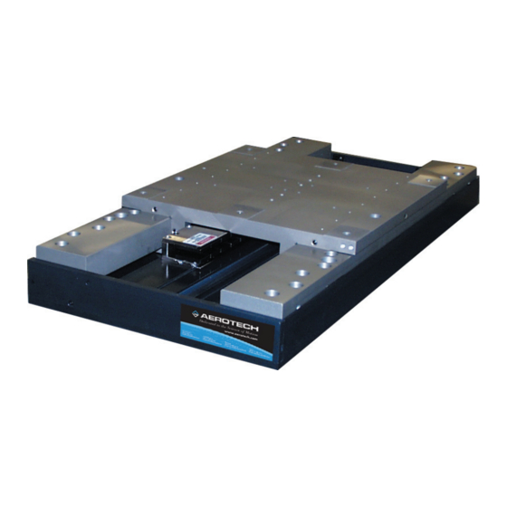
ABL8000 User's Manual Overview Chapter 1: Overview This manual describes Aerotech’s ABL8000 series of air bearing positioning stages. Figure 1-1 shows a typ- ical ABL8000 positioning stage. The ABL8000 series stages supports travel distances ranging from 200 mm to 1000 mm. The -LC con- struction of the ABL8000 has a long carriage that is optimized for load capacity and stiffness, and it is typ- ically used as the lower axis of an XY stage stack. -
Page 8: Standard Features
The brushless linear motor uses an ironless forcer, which means there is zero cogging and no attractive forces – resulting in unsurpassed smoothness of motion. This is especially useful in applications where velocity control is important. Figure 1-2: ABL8000 Series Stage Chapter 1 www.aerotech.com... -
Page 9: Optional Features
1.1.1. Optional Features The ABL8000 can be readily customized to meet the needs of individual applications. Common examples include cable management for stage-mounted payloads, custom tabletops, and granite bases. Contact the Aerotech factory for details. Table 1-1: Ordering Example (ABL80050-LC-M-P-NC-LN50AS-SINGLE-CMS) -
Page 10: Dimensions
400.0 [16.00] 736.6 [29.00] 228.6 [9.00] ABL80050-SC 500.0 [16.00] 838.2 [33.00] 228.6 [9.00] ABL80075-SC 750.0 [30.00] 1092.2 [43.00] 228.6 [9.00] 285.8 [11.25] ABL80100-SC 1000.0 [40.00] 1346.2 [43.00] 228.6 [9.00] 285.8 [11.25] Figure 1-3: ABL8000 Stage Dimensions (-SC Option) Chapter 1 www.aerotech.com... -
Page 11: Figure 1-4: Abl8000 Stage Dimensions (-Lc Option)
400.0 [16.00] 889.0 [35.00] 228.6 [9.00] ABL80050-LC 500.0 [16.00] 990.6 [39.00] 228.6 [9.00] ABL80075-LC 750.0 [30.00] 1244.6 [49.00] 228.6 [9.00] 285.8 [11.25] ABL80100-LC 1000.0 [40.00] 1498.6 [59.00] 228.6 [9.00] 285.8 [11.25] Figure 1-4: ABL8000 Stage Dimensions (-LC Option) www.aerotech.com Chapter 1... -
Page 12: Safety Procedures And Warnings
Use of the ABL8000 for unintended applications can result in injury and damage to the equip- ment. W A R N I N G : Before using this ABL8000, perform an operator risk assessment to determine the needed safety requirements. Chapter 1 www.aerotech.com... -
Page 13: Ec Declaration Of Incorporation
101 Zeta Drive Pittsburgh, PA 15238 herewith declares that the product: Aerotech, Inc. ABL8000 Stage is intended to be incorporated into machinery to constitute machinery covered by the Directive 2006/42/EC as amended; does therefore not in every respect comply with the provisions of this directive;... - Page 14 Overview ABL8000 User's Manual Chapter 1 www.aerotech.com...
-
Page 15: Chapter 2: Installation
W A R N I N G : Installation must follow the instructions in this chapter. Failure to follow these instructions could result in injury and damage to the equipment. www.aerotech.com Chapter 2... -
Page 16: Unpacking And Handling The Stage
Aerotech. Use compressed nitrogen or clean, dry, oil-less air to remove any dust or debris that has collected during shipping. Set the ABL8000 on a smooth, flat, and clean surface. -
Page 17: Preparing The Mounting Surface
If machining is required to achieve the desired flatness, it should be performed on the mounting surface rather than the ABL8000 base. Shimming should be avoided if possible. If shimming is required, it should be minimized to improve the rigidity of the system. www.aerotech.com Chapter 2... -
Page 18: Securing The Stage To The Mounting Surface
7. Slide the air-bearing carriage to the opposite end of travel and install the stage mounting screws in the exposed mounting holes. As in step 6, do not tighten the screws yet, but bring within 1/4 turn of Chapter 2 www.aerotech.com... -
Page 19: Figure 2-4: Mounting Holes In The Stage Table
Figure 2-4: Mounting Holes in the Stage Table 9. Tighten the mounting screws (begin from the center out for best accuracy). The usual torque value for M6 socket head cap screws is 8 N-m . www.aerotech.com Chapter 2... -
Page 20: Attaching The Payload To The Stage
Aerotech motion control systems are adjusted at the factory for optimum performance. When the ABL8000 is part of a complete Aerotech motion control system, setup usually involves connecting a stage to the appro- priate drive chassis with the cables provided. Labels on the system components usually indicate the appro- priate connections. -
Page 21: Figure 2-6: Motor And Feedback Connections (-Xy-Cms Option)
ABL8000 User's Manual Installation Figure 2-6: Motor and Feedback Connections (-XY-CMS option) Figure 2-7: Motor and Feedback Connections (-XY-CMS Customer Cable option) Figure 2-8: Motor and Feedback Connections (-XY-CMS Customer Hose option) www.aerotech.com Chapter 2... -
Page 22: Air Requirements
For the -SC construction, an airflow rate of between 30 to 36 SLPM (standard liters per minute) at 551 kPa should be observed (single axis). For the -LC construction, an airflow rate of between 48 to 53 SLPM (stand- ard liters per minute) at 551 kPa should be observed (single axis). Figure 2-10: Air Fitting Location Chapter 2 www.aerotech.com... -
Page 23: Chapter 3: Operating Specifications
Altitude Operating: 0 to 2,000 m (0 to 6,562 ft) above sea level Contact Aerotech if your specific application involves use above 2,000 m or below sea level. Vibration Use the system in a low vibration environment. Contact Aerotech for information regarding your specific application. -
Page 24: Basic Specifications
Operating Specifications ABL8000 User's Manual 3.3. Basic Specifications For the most recent specifications, see www.aerotech.com. Table 3-2: Series Specifications (ABL80020 - ABL80040) ABL80020 ABL80030 ABL80040 Travel 200 mm 300 mm 400 mm Accuracy LN Standard ±5.0 µm [±200 µin] LT Standard ±8.0 µm [±315 µin] ±11.5 µm [±453 µin]... -
Page 25: Table 3-3: Series Specifications (Abl80050 - Abl80100)
(5) Thermal limitations of positioning stage with respect to performance may limit continuous force output. (6) Force may be limited by amplifier output. (7) Available with Aerotech controllers. (8) Requires environmental compensation. (9) To protect air bearing against under-pressure, an in-line pressure switch tied to controller ESTOP input is recommended. -
Page 26: Table 3-4: Electrical Specifications
Recommended Controller Multi Axis A3200/ Ndrive MP / Ndrive CP / Ndrive HLe / Npaq MXR Ensemble Ensemble MP / Ensemble CP / Ensemble HLe / Epaq Single Axis Soloist SoloistMP / Soloist CP / Soloist HLe Chapter 3 www.aerotech.com... -
Page 27: Table 3-6: Abl8000 Series Motor Specifications
(6) Maximum winding temperature is °C (7) Ambient operating temperature range: 0 °C - 25 °C, consult Aerotech for performance in elevated ambient temperatures (8) All Aerotech amplifiers are rated Apk; use torque constant in N-m / Apk when sizing www.aerotech.com... -
Page 28: Load Capability
ABL8000-SC stages and 120 kg for ABL8000-LC stages. If cantilevered loads are applied, refer to Figure 3-1 Figure 3-2 to find the maximum allowable load. Horizontal Side Distance of Load C.G. from Tabletop Centerline (mm) Figure 3-1: Cantilevered Load Capability (-SC Construction) Chapter 3 www.aerotech.com... -
Page 29: Figure 3-2: Cantilevered Load Capability (-Lc Construction)
ABL8000 User's Manual Operating Specifications Horizontal Side Distance of Load C.G. from Tabletop Centerline (mm) Figure 3-2: Cantilevered Load Capability (-LC Construction) www.aerotech.com Chapter 3... -
Page 30: Figure 3-3: Cantilever Length Diagram
Operating Specifications ABL8000 User's Manual Side Load C.G. Horizontal Load Figure 3-3: Cantilever Length Diagram Chapter 3 www.aerotech.com... -
Page 31: End Of Travel Limits
Normally Closed Normally Open Pull-Up Resistor Pull-Up Resistor Limit Input Limit Input to Controller to Controller Normally Closed Normally Open Limit Switch (NC) Limit Switch (NO) Figure 3-4: Normally Closed (NC) and Normally Open (NO) Limit Switch Wiring www.aerotech.com Chapter 3... -
Page 32: Standard Motor Wiring
Motor Connector Pin Assignments Description Connector MTR ØA (Motor Phase A) MTR ØB (Motor Phase B) MTR ØC (Motor Phase C) Shield for motor wiring connector Reserved: Not Used Reserved: Not Used Reserved: Not Used Reserved: Not Used Ground to stage base Chapter 3 www.aerotech.com... -
Page 33: Vacuum Operation
Common ground to encoder power. -Limit / CCW Signal indicating maximum travel produced by positive/CW stage direction. 3.7. Vacuum Operation The ABL8000 is an air-bearing stage and is not compatible with operation in a vacuum environment. Contact Aerotech for alternate solutions. www.aerotech.com Chapter 3... - Page 34 Operating Specifications ABL8000 User's Manual Chapter 3 www.aerotech.com...
-
Page 35: Chapter 4: Maintenance
D A N G E R : To minimize the possibility of bodily injury or death, disconnect all electrical power prior to making any mechanical adjustments. 4.1. Service and Inspection Schedule Aerotech recommends that the ABL8000 stage be inspected once per month until a trend develops for the specific application and environment. 4.2. Cleaning and Lubrication There are no elements on the ABL8000 that require lubrication. -
Page 36: Cleaning Process
D A N G E R : To minimize the possibility of bodily injury or death, disconnect all electrical power prior to making any mechanical adjustments. Chapter 4 www.aerotech.com... -
Page 37: Appendix A: Warranty And Field Service
Aerotech makes no warranty that its products are fit for the use or purpose to which they may be put by the buyer, where or not such use or purpose has been disclosed to Aero-... - Page 38 Warranty and Field Service ABL8000 User's Manual On-site Warranty Repair If an Aerotech product cannot be made functional by telephone assistance or by send- ing and having the customer install replacement parts, and cannot be returned to the Aerotech service center for repair, and if Aerotech determines the problem could be...
-
Page 39: Appendix B: Revision History
ABL8000 User's Manual Revision History Appendix B: Revision History Rev # Date Description 1.00.00 March 12, 2012 New Manual www.aerotech.com Appendix B... - Page 40 Revision History ABL8000 User's Manual Appendix B www.aerotech.com...
-
Page 41: Index
EOT 25 Inspection Schedule 29 Installation 9 Limit Switch Operation 25 Limit Switch Wiring 25 Load Capability 22 Lubrication 29 Maintenance 29 model numbers 10 Motor and Feedback Connections 14-16 Operating Specifications 17 Optional Features 3 Overview 1 www.aerotech.com Index... - Page 42 ABL8000 User's Manual Index Index www.aerotech.com...
Need help?
Do you have a question about the ABL8000 Series ABL80020 and is the answer not in the manual?
Questions and answers