Table of Contents
Advertisement
Quick Links
Advertisement
Table of Contents

Related Manuals for Aerotech ASR1300


Summary of Contents for Aerotech ASR1300
-
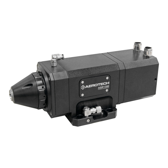
Page 1: Asr1300 Rotary Stage Hardware Manual
ASR1300 Rotary Stage Hardware Manual Revision: 1.01.00... - Page 2 This manual contains proprietary information and may not be reproduced, disclosed, or used in whole or in part without the express written permission of Aerotech, Inc. Product names mentioned herein are used for identification purposes only and may be trademarks of their respective companies.
-
Page 3: Table Of Contents
ASR1300 Hardware Manual Table of Contents Table of Contents ASR1300 Rotary Stage Hardware Manual Table of Contents List of Figures List of Tables Safety Procedures and Warnings EU Declaration of Incorporation Chapter 1: Overview 1.1. Environmental Specifications 1.2. Accuracy and Temperature Effects 1.3. -
Page 4: List Of Figures
Table of Contents ASR1300 Hardware Manual List of Figures Figure 2-1: ASR1300 Dimensions Figure 2-2: ASR1300 Stage Showing Mounting Plate (Top View) Figure 2-3: ASR1300 Stage Without Mounting Plate (Bottom View) Figure 2-4: Collet Installation Figure 2-5: Material Guide Tube Installation... -
Page 5: List Of Tables
ASR1300 Hardware Manual Table of Contents List of Tables Table 1-1: Model Options Table 1-2: Environmental Specifications Table 1-3: ASR1300 Series Specifications Table 2-1: Stage to Mounting Surface Hardware Table 3-1: 4-Pin HPD Motor Connector Pinouts (-CN1 Option) Table 3-2: 4-Pin D Motor Mating Connector Table 3-3: 25-Pin D Motor Connector Pinouts (-CN2 Option) -
Page 6: Safety Procedures And Warnings
Safety Procedures and Warnings This manual tells you how to carefully and correctly use and operate the ASR1300. Read all parts of this manual before you install or operate the ASR1300 or before you do maintenance to your system. To prevent injury to you and damage to the equipment, obey the precautions in this manual. -
Page 7: Eu Declaration Of Incorporation
ASR1300 Hardware Manual Table of Contents EU Declaration of Incorporation Manufacturer: Aerotech, Inc. 101 Zeta Drive Pittsburgh, PA 15238-2811 herewith declares that the product: ASR1300 Stage is intended to be incorporated into machinery to constitute machinery covered by the Directive 2006/42/EC as amended;... - Page 8 Table of Contents ASR1300 Hardware Manual This page intentionally left blank. www.aerotech.com...
-
Page 9: Chapter 1: Overview
Mounting plate - with water cooling Note: ASR1300 stages can be configured to include a mounting plate. The bottom of this mounting plate is precision machined and verified for flatness. If the mounting plate is not selected, a custom mounting option can be attached using the [QTY-4] M5 tapped holes in the bottom of the stage. -
Page 10: Environmental Specifications
Extreme temperature changes could cause a decrease in performance or permanent damage to the stage. Aerotech stages are designed for and built in a 20°C (68°F) environment. Any deviation from standard operating temperature will affect stage accuracy. The severity of temperature effects on all stage specifications depends on many different environmental conditions, including how the stage is mounted. -
Page 11: Basic Specifications
2. Based on steady-state temperature rise of motor by 20°C from ambient with Water Cooling option. Continuous accel limit is 1600 rad/s² without Water Cooling option. 3. Maximum loads are mutually exclusive. Loading limits are due to the collet chuck mechanism. Contact Aerotech directly if part load requirement exceeds specifications. - Page 12 Overview ASR1300 Hardware Manual This page intentionally left blank. Chapter 1 www.aerotech.com...
-
Page 13: Chapter 2: Installation
Installation Chapter 2: Installation W A R N I N G : ASR1300 installation must be in accordance to instructions provided by this manual and any accompanying documentation. Failure to follow these instructions could result in injury or damage to the equipment. -
Page 14: Dimensions
Installation ASR1300 Hardware Manual 2.2. Dimensions Figure 2-1: ASR1300 Dimensions Chapter 2 www.aerotech.com... -
Page 15: Securing The Stage To The Mounting Surface
Installation 2.3. Securing the Stage to the Mounting Surface W A R N I N G : Do not attempt to manually move the ASR1300 if it is connected to a power source. W A R N I N G : Make sure that all moving parts are secure before moving the ASR1300. -
Page 16: Figure 2-2: Asr1300 Stage Showing Mounting Plate (Top View)
Installation ASR1300 Hardware Manual Figure 2-2: ASR1300 Stage Showing Mounting Plate (Top View) Figure 2-3: ASR1300 Stage Without Mounting Plate (Bottom View) Chapter 2 www.aerotech.com... -
Page 17: Air Requirements
5.5-7 bar (80-100 psig). Lower pressures, greater than 4 bar (60 psi), can be used but would be application specific. Aerotech recommends using the minimum pressure required for the application that securely clamps the work piece. Lower pressures reduce the possibility of workpiece damage, and ensure the highest system performance. -
Page 18: General Mechanical Setup
2.7.). Appropriately sized material can then be inserted in to the collet. The collet chuck should again be checked for proper operation using the same procedures as before. Aerotech recommends turning the air pressure supply to 0 psi using a precision regulator and slowly increasing pressure until the material is clamped in the collet. -
Page 19: Load Capability
ASR1300 Hardware Manual Installation 2.6. Load Capability The ASR1300 is designed for tubular manufacturing applications. With this in mind, the tubes loaded into the collet chuck of the rotary axis must fall within the maximum load parameters in Section 1.3. -
Page 20: Changing Asr Workholding Devices
ASR1300 Hardware Manual 2.7. Changing ASR Workholding Devices ASR1300 stages are equipped with Levin “Type-D” style collets. It is important that only the collets designed for a particular collet holder are used. Contact the factory for more details. N O T E : Various grip diameters are commonly available and can be interchanged. -
Page 21: Figure 2-4: Collet Installation
ASR1300 Hardware Manual Installation Figure 2-4: Collet Installation To Remove a Collet: Step 1: Disable and remove power to the stage. Step 2: Turn off air pressure to expose the front of collet in chuck Figure 2-4. Step 3: Unthread the collet from chuck by turning counter-clockwise. -
Page 22: Collet Chuck Tube Guide
2.8. Collet Chuck Tube Guide The material guide tube has a 2.5 mm hex broach that can be accessed from the front side of ASR1300. The guide tube is used to help pilot small diameter tubes through the transition from the shaft aperture to the collet. -
Page 23: Figure 2-5: Material Guide Tube Installation
ASR1300 Hardware Manual Installation Figure 2-5: Material Guide Tube Installation www.aerotech.com Chapter 2... -
Page 24: Motor Cooling With The Motor Plate
Installation ASR1300 Hardware Manual 2.9. Motor Cooling with the Motor Plate The [Qty-2] compression fittings located on both sides of the housing are design for 4 mm O.D. “stiff wall” tube. Stainless steel barb inserts are included with each stage for a 2 mm I.D. tube. -
Page 25: Chapter 3: Electrical Specifications And Installation
Aerotech motion control systems are adjusted at the factory for optimum performance. When the ASR1300 is part of a complete Aerotech motion control system, setup usually involves connecting the ASR1300 to the appropriate drive chassis with the cables provided. Labels on the system components usually indicate the appropriate connections. -
Page 26: Motor And Feedback Connectors
Stages equipped with standard motors and encoders come from the factory completely wired and assembled. N O T E : If using standard Aerotech motors and cables, motor and encoder connection adjustments are not required. The protective ground connection of the ASR1300 provides motor frame ground protection only. Additional grounding and safety precautions are required for applications requiring access to the stage while it is energized. -
Page 27: Table 3-3: 25-Pin D Motor Connector Pinouts (-Cn2 Option)
ASR1300 Hardware Manual Operating Specifications Table 3-3: 25-Pin D Motor Connector Pinouts (-CN2 Option) Description Connector Motor Shield (EMI shield) Frame Ground Frame Ground Frame Ground Motor Phase C Motor Phase B Motor Phase A Pins 3, 7, 10, 16, 19, and 23 have been removed. -
Page 28: Table 3-5: 25-Pin D Feedback Connector Pinouts
Operating Specifications ASR1300 Hardware Manual Table 3-5: 25-Pin D Feedback Connector Pinouts Description Connector Signal shield connection Reserved +5 V power supply (the typical requirement is 250 mA). Reserved Reserved Marker-N Marker Reserved Reserved Reserved Reserved Reserved Reserved Cosine Cosine-N +5 V power supply... -
Page 29: Motor And Feedback Wiring
ASR1300 Hardware Manual Operating Specifications 3.2. Motor and Feedback Wiring Shielded cables are required for the motor and feedback connections. Figure 3-1: Motor and Feedback Wiring (-CN1 Option) www.aerotech.com Chapter 3... -
Page 30: Figure 3-2: Motor And Feedback Wiring (-Cn2 Option)
Operating Specifications ASR1300 Hardware Manual Figure 3-2: Motor and Feedback Wiring (-CN2 Option) Chapter 3 www.aerotech.com... -
Page 31: Motor And Feedback Specifications
5. Torque constant and motor constant specified at stall 6. Maximum winding temperature is 130 °C 7. Ambient operating temperature range 0 °C - 25 °C; consult Aerotech for performance in elevated ambient temperatures 8. All Aerotech amplifiers are rated A ;... -
Page 32: Machine Direction
Operating Specifications ASR1300 Hardware Manual 3.4. Machine Direction Aerotech stages are configured to have positive and negative "machine" directions. The machine direction defines the phasing of the feedback and motor signals and is dictated by the stage wiring (refer to Section 3.5. -
Page 33: Motor And Feedback Phasing
ASR1300 Hardware Manual Operating Specifications 3.5. Motor and Feedback Phasing Motor phase voltage is measured relative to the virtual wye common point. Figure 3-4: Motor Phasing www.aerotech.com Chapter 3... -
Page 34: Figure 3-5: Analog Encoder Phasing Reference Diagram
Operating Specifications ASR1300 Hardware Manual Figure 3-5: Analog Encoder Phasing Reference Diagram Chapter 3 www.aerotech.com... -
Page 35: Chapter 4: Maintenance
4.1. Service and Inspection Schedule A frequent inspection and cleaning interval of the ASR1300 series stages is recommended until a trend develops for the application. The inspection and cleaning interval depends on application conditions such as duty cycle, speed, and environment. -
Page 36: Cleaning And Lubrication
ASR1300 Hardware Manual 4.2. Cleaning and Lubrication Before using a cleaning solvent on any part of the ASR1300, blow away small particles and dust with nitrogen or, less preferably, clean, dry, compressed air. Any metal surface on the stage can be cleaned with either acetone or isopropyl alcohol. Cleaning solvents, especially acetone, should not be used on any rubber components (o-rings and seals). -
Page 37: Collet And Collet Chuck Cleaning And Lubrication
If the wear marks are large, or excessive polishing is required to remove these marks, the collet chuck and collet may need to be replaced. Contact Aerotech Technical Support for more information. Wear and fretting can be prevented with proper lubrication and maintenance intervals. -
Page 38: Figure 4-1: Collet And Collet Chuck Lubrication
Maintenance ASR1300 Hardware Manual Figure 4-1: Collet and Collet Chuck Lubrication Chapter 4 www.aerotech.com... -
Page 39: Piston Seal Lubrication
Eccentricity Alignment in the collet chuck and Balancing in the spindle. N O T E : Aerotech recommends that you return the unit to the factory to be serviced by a qualified Aerotech technician. -
Page 40: Seal Replacement
Alignment in the collet chuck and Balancing in the spindle. The collet chuck on the ASR1300 is equipped with a piston that uses O-ring seals. The seals are designed to last many collet chuck (open/close) cycles. However, due to regular wear, the seals can require replacement during the lifetime of the product. -
Page 41: Troubleshooting
ASR1300 Hardware Manual Maintenance 4.4. Troubleshooting This section provides some information regarding typical problems. Table 4-2: Troubleshooting Symptom Possible Cause and Solution Stage will not move Controller trap or fault (refer to the Controller documentation). Encoder (sine and cosine) signal connections (refer to... - Page 42 Maintenance ASR1300 Hardware Manual This page intentionally left blank. Chapter 4 www.aerotech.com...
-
Page 43: Appendix A: Warranty And Field Service
Aerotech makes no warranty that its products are fit for the use or purpose to which they may be put by the buyer, whether or not such use or purpose has been disclosed to Aerotech in specifications or drawings previously or subsequently provided, or whether or not Aerotech’s... - Page 44 Aerotech's approval. On-site Warranty Repair If an Aerotech product cannot be made functional by telephone assistance or by sending and having the customer install replacement parts, and cannot be returned to the Aerotech service center for repair, and if Aerotech determines the problem could be warranty-related, then the following policy applies:...
-
Page 45: Appendix C: Revision History
ASR1300 Hardware Manual Revision History Appendix C: Revision History Revision General Information 1.01.00 Updated air filtration specification from 0.25 µm to 1.0 µm (Section 2.4.) 1.00.00 New manual www.aerotech.com Appendix B... - Page 46 Revision History ASR1300 Hardware Manual This page intentionally left blank. Appendix B www.aerotech.com...
-
Page 47: Index
ASR1300 Hardware Manual Index Index Encoder Specifications 2010 Global Technical Support accuracy and temperature Humidity compressed inspection schedule nitrogen installation requirements collet Altitude Ambient Temperature label load capability changing ASR workholding devices lubrication cleaning collet chuck collet collet/collet chuck maintenance... - Page 48 Index ASR1300 Hardware Manual requirements seal replacement Securing the Stage to the Mounting Surface serial number service schedule shimming specifications temperature Specifications stabilizing stage stage distortion stabilizing Support Technical Support temperature and accuracy Unpacking and Handling the Stage Vibration Warranty and Field Service...
Need help?
Do you have a question about the ASR1300 and is the answer not in the manual?
Questions and answers