Table of Contents
Advertisement
Quick Links
Advertisement
Table of Contents

Related Manuals for Aerotech ASRT Series


Summary of Contents for Aerotech ASRT Series
-
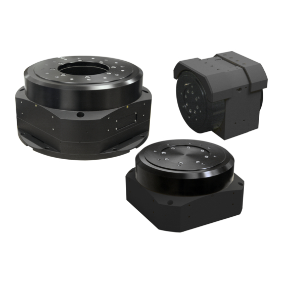
Page 1: Asrt Hardware Manual
ASRT Hardware Manual Revision: 1.01.00... - Page 2 This manual contains proprietary information and may not be reproduced, disclosed, or used in whole or in part without the express written permission of Aerotech, Inc. Product names mentioned herein are used for identification purposes only and may be trademarks of their respective companies.
-
Page 3: Table Of Contents
3.5. Motor and Feedback Phasing Chapter 4: Maintenance 4.1. Service and Inspection Schedule 4.1.1. Ground Brushes 4.1.2. Drainage Plumbing 4.1.3. Desiccant Cartridge 4.2. Cleaning and Lubrication 4.3. Troubleshooting Appendix A: Warranty and Field Service Appendix B: Revision History Index www.aerotech.com... -
Page 4: List Of Figures
Table of Contents ASRT Hardware Manual List of Figures Figure 1-1: ASRT Series Torque Capacity Figure 1-2: ASRT Series Current Capacity Figure 2-1: ASRT185 Dimensions Figure 2-2: ASRT185 Dimensions (Horizontal Mounting with Shroud) Figure 2-3: ASRT245 Dimensions Figure 2-4: ASRT245 Dimensions (Horizontal Mounting with Shroud) -
Page 5: List Of Tables
Table of Contents List of Tables Table 1-1: Model Numbers and Ordering Options Table 1-2: Environmental Specifications Table 1-3: ASRT Series Specifications Table 2-1: Stage to Mounting Surface Hardware Table 3-1: Motor Wiring Connector Table 3-2: Feedback Connector (-E1 or -E3 Encoder Option) -
Page 6: Safety Procedures And Warnings
Read this manual in its entirety before installing, operating, or servicing this product. If you do not understand the information contained herein, contact an Aerotech representative before proceeding. Strictly adhere to the statements given in this section and other handling, use, and operational information given throughout the manual to avoid injury to you and damage to the equipment. -
Page 7: Eu Declaration Of Incorporation
ASRT Hardware Manual Table of Contents EU Declaration of Incorporation Manufacturer: Aerotech, Inc. 101 Zeta Drive Pittsburgh, PA 15238-2811 herewith declares that the product: ASRT Stage is intended to be incorporated into machinery to constitute machinery covered by the Directive 2006/42/EC as amended;... - Page 8 Table of Contents ASRT Hardware Manual This page intentionally left blank. www.aerotech.com...
-
Page 9: Chapter 1: Overview
Overview Chapter 1: Overview N O T E : Aerotech continually improves its product offerings; listed options may be superseded at any time. All drawings and illustrations are for reference only and were complete and accurate as of this manual’s release. Refer to www.aerotech.com for the most up-to-date information. -
Page 10: Environmental Specifications
Extreme temperature changes could cause a decrease in performance or permanent damage to the stage. Aerotech stages are designed for and built in a 20°C (68°F) environment. Any deviation from standard operating temperature will affect stage accuracy. The severity of temperature effects on all stage specifications depends on many different environmental conditions, including how the stage is mounted. -
Page 11: Basic Specifications
Overview 1.3. Basic Specifications N O T E : Aerotech continually improves its product offerings; listed options may be superseded at any time. All drawings and illustrations are for reference only and were complete and accurate as of this manual’s release. Refer to www.aerotech.com for the most up-to-date information. -
Page 12: Figure 1-1: Asrt Series Torque Capacity
Overview ASRT Hardware Manual Figure 1-1: ASRT Series Torque Capacity Figure 1-2: ASRT Series Current Capacity Chapter 1 www.aerotech.com... -
Page 13: Chapter 2: Mechanical Specifications And Installation
Allowing it to stabilize to room temperature will ensure that all of the alignments, preloads, and tolerances are the same as they were when tested at Aerotech. Use compressed nitrogen or clean, dry, oil-less air to remove any dust or debris that has collected during shipping. -
Page 14: Dimensions
Assembly and Installation ASRT Hardware Manual 2.2. Dimensions Figure 2-1: ASRT185 Dimensions Chapter 2 www.aerotech.com... -
Page 15: Figure 2-2: Asrt185 Dimensions (Horizontal Mounting With Shroud)
ASRT Hardware Manual Assembly and Installation Figure 2-2: ASRT185 Dimensions (Horizontal Mounting with Shroud) www.aerotech.com Chapter 2... -
Page 16: Figure 2-3: Asrt245 Dimensions
Assembly and Installation ASRT Hardware Manual Figure 2-3: ASRT245 Dimensions Chapter 2 www.aerotech.com... -
Page 17: Figure 2-4: Asrt245 Dimensions (Horizontal Mounting With Shroud)
ASRT Hardware Manual Assembly and Installation Figure 2-4: ASRT245 Dimensions (Horizontal Mounting with Shroud) www.aerotech.com Chapter 2... -
Page 18: Figure 2-5: Asrt300 Dimensions
Assembly and Installation ASRT Hardware Manual Figure 2-5: ASRT300 Dimensions Chapter 2 www.aerotech.com... -
Page 19: Figure 2-6: Asrt300 Dimensions (Horizontal Mounting With Shroud)
ASRT Hardware Manual Assembly and Installation Figure 2-6: ASRT300 Dimensions (Horizontal Mounting with Shroud) www.aerotech.com Chapter 2... -
Page 20: Securing The Stage To The Mounting Surface
Shimming should be avoided if possible. If shimming is required, it should be minimized to improve the rigidity of the system. ASRT series stages have a fixed mounting pattern (as shown in Figure 2-7). -
Page 21: Figure 2-7: Vertical Axis Of Rotation Mounting Counter-Bored Holes
20 N·m Standard Mounting (through holes) ASRT-185: M6 SHCS 8 N·m ASRT-245: M6 SHCS 8 N·m ASRT-300: M8 SHCS 20 N·m Side Mounting ASRT-185: M6x1 8 N·m ASRT-245: M8x1.25 20 N·m ASRT-300: M8x1.25 20 N·m Figure 2-7: Vertical Axis of Rotation Mounting Counter-bored Holes www.aerotech.com Chapter 2... -
Page 22: Figure 2-8: Vertical Axis Of Rotation Flange Mounting Through Holes
Assembly and Installation ASRT Hardware Manual Figure 2-8: Vertical Axis of Rotation Flange Mounting Through Holes Figure 2-9: Horizontal Axis of Rotation Side Mounting Tapped Holes Chapter 2 www.aerotech.com... -
Page 23: Attaching The Payload To The Stage
N O T E : If your ASRT was purchased with Aerotech controls, it might have been tuned with a representative payload based on the information provided at the time of order. If the ASRT is started up without a payload, the servo gains provided by Aerotech with the shipment may not be appropriate and servo instability can occur. -
Page 24: Figure 2-11: Asrt245 Load Curves
Assembly and Installation ASRT Hardware Manual Figure 2-11: ASRT245 Load Curves Figure 2-12: ASRT300 Load Curves Chapter 2 www.aerotech.com... -
Page 25: Horizontal Axis Of Rotation Mounting
Any mounting fixtures should leave access to the connectors, air fitting, and ground lug. The fixtures should also have a water channel around the hole plug to allow adequate drainage. Figure 2-14: Drainage Plug Location www.aerotech.com Chapter 2... -
Page 26: Air Purge Fitting
1/8 NPT pipe thread. Without this option, the ASRT ships with a 1/8 NPT plug. All threads are wrapped with Teflon tape at the factory to ensure good sealing. Figure 2-15: Air Purge Fitting Accessory Chapter 2 www.aerotech.com... -
Page 27: Chapter 3: Electrical Installation
Electrical installation requirements will vary depending on product options. Installation instructions in this section are for ASRTs equipped with standard Aerotech motors intended for use with an Aerotech motion control system. Contact Aerotech for further information regarding products that are otherwise configured. -
Page 28: Motor And Feedback Connectors
Stages equipped with standard motors and encoders come from the factory completely wired and assembled. N O T E : If using standard Aerotech motors and cables, motor and encoder connection adjustments are not required. The protective ground connection of the ASRT provides motor frame ground protection only. Additional grounding and safety safeguards are required for applications requiring access to the stage while it is energized. -
Page 29: Table 3-2: Feedback Connector (-E1 Or -E3 Encoder Option)
+5 V power supply limit input Encoder +5 V power supply input (internally connected to Pin 20) Encoder Common (internally connected to Pin 21) NOTE: Pins not listed are RESERVED. Mating Connector Aerotech P/N Third Party P/N Connector ECK01821 PEI, MS27473T14F35S-CG O-Ring ECK01822 Conta-Clip, 23233.9... -
Page 30: Table 3-3: Feedback Connector (-E2 Encoder Option)
+5 V power supply limit input Encoder +5 V power supply input (internally connected to Pin 20) Encoder Common Differential compliment of CLK signal NOTE: Pins not listed are RESERVED. Mating Connector Aerotech P/N Third Party P/N Connector ECK01821 PEI, MS27473T14F35S-CG O-Ring ECK01822 Conta-Clip, 23233.9... -
Page 31: Ground Attachments
Electrical Specifications and Installation 3.1.1. Ground Attachments ASRT series stages come with two ground lugs: one for stage ground and one for payload ground. The stage ground is located adjacent to the connectors, and the payload ground is located on the tabletop. -
Page 32: Motor And Feedback Wiring
Electrical Specifications and Installation ASRT Hardware Manual 3.2. Motor and Feedback Wiring Shielded cables are required for the motor and feedback connections. Figure 3-4: Motor and Feedback Wiring (Encoder Option -E1 or -E3) Chapter 3 www.aerotech.com... -
Page 33: Figure 3-5: Motor And Feedback Wiring (Encoder Option -E2)
ASRT Hardware Manual Electrical Specifications and Installation Figure 3-5: Motor and Feedback Wiring (Encoder Option -E2) www.aerotech.com Chapter 3... -
Page 34: Motor And Feedback Specifications
Supply Current 250 mA Sinusoidal Type (Incremental Encoder): 1 V into 120 Ω Load (differential pk-pk signals SIN+, SIN-, COS+, COS- are .5 V relative to ground.) pk-pk Output Signals Digital Output (Incremental Encoder): RS422/485 compatible Serial Output (Absolute Encoder): Biss C (unidirectional) Chapter 3 www.aerotech.com... -
Page 35: Table 3-5: S-130-39-A Motor Specifications (For Asrt185Dr)
6. Specifications given are for the motor only. When integrated into a housing with bearings additional losses should be considered. 7. Maximum winding temperature is 100 °C (thermistor trips at 100 °C) 8. Ambient operating temperature range 0 °C - 25 °C; consult Aerotech for performance in elevated ambient temperatures 9. All Aerotech amplifiers are rated A ;... -
Page 36: Table 3-6: S-180-44-B Motor Specifications (For Asrt245Dr)
6. Specifications given are for the motor only. When integrated into a housing with bearings additional losses should be considered. 7. Maximum winding temperature is 100 °C (thermistor trips at 100 °C) 8. Ambient operating temperature range 0 °C - 25 °C; consult Aerotech for performance in elevated ambient temperatures 9. All Aerotech amplifiers are rated A ;... -
Page 37: Table 3-7: S-240-43-A Motor Specifications (For Asrt300Dr)
6. Specifications given are for the motor only. When integrated into a housing with bearings additional losses should be considered. 7. Maximum winding temperature is 100 °C (thermistor trips at 100 °C) 8. Ambient operating temperature range 0 °C - 25 °C; consult Aerotech for performance in elevated ambient temperatures 9. All Aerotech amplifiers are rated A ;... -
Page 38: Limits, Marker, And Machine Direction
ASRT Hardware Manual 3.4. Limits, Marker, and Machine Direction Aerotech stages are configured to have positive and negative "machine" directions. The machine direction defines the phasing of the feedback and motor signals and is dictated by the stage wiring (refer to Section 3.5. -
Page 39: Motor And Feedback Phasing
ASRT Hardware Manual Electrical Specifications and Installation 3.5. Motor and Feedback Phasing Motor phase voltage is measured relative to the virtual wye common point. Figure 3-7: Hall Phasing www.aerotech.com Chapter 3... -
Page 40: Figure 3-8: Analog Encoder Phasing Reference Diagram
Electrical Specifications and Installation ASRT Hardware Manual Figure 3-8: Analog Encoder Phasing Reference Diagram Figure 3-9: Encoder Phasing Reference Diagram (Standard) Chapter 3 www.aerotech.com... -
Page 41: Chapter 4: Maintenance
Maintenance Chapter 4: Maintenance The ASRT series stages are designed to require minimum maintenance. D A N G E R : To minimize the possibility of bodily injury or death, disconnect all electrical power prior to performing any maintenance or making adjustments to the equipment. -
Page 42: Ground Brushes
Insert screws but do not tighten them. Rotate the shaft one turn to make sure the cover does rub against the housing, and then tighten the screws. Figure 4-2: Rear Shaft Cover and Brushes Location Chapter 4 www.aerotech.com... -
Page 43: Drainage Plumbing
1/8 NPT plug (see Figure 4-3) and supplying nitrogen to the opening. Reinstall all plugs after flushing trapped water. Figure 4-3: Drainage Plug Locations www.aerotech.com Chapter 4... -
Page 44: Desiccant Cartridge
Beaded Blue indicating Sodium alumina silicate with an inorganic metal salt moisture indicator. MCA55623: Desiccant beads MPH27012-01: Desiccant Cartridge Kit, ASRT185DR Aerotech P/Ns MPH27012-02: Desiccant Cartridge Kit, ASRT245DR MPH27012-03: Desiccant Cartridge Kit, ASRT300DR Manufacturer's P/N LabSorbents mSORB® Item # L-4A48B-IMS-800GB Chapter 4... -
Page 45: Cleaning And Lubrication
Any external metal surface of the ASRT can be cleaned with isopropyl alcohol on a lint-free cloth. W A R N I N G : Make sure that all solvent has completely evaporated before attempting to move the stage. Lubrication There are no elements on ASRT stages that require lubrication. www.aerotech.com Chapter 4... -
Page 46: Troubleshooting
Controller trap or fault. See controller documentation. Stage moves uncontrollably Encoder (sine and cosine) signals connections. See Chapter 3 Controller documentation. Motor Connections. See Chapter 3 and Controller documentation. Stage oscillates or squeals Gains misadjusted. See Controller documentation. Encoder signals. See Controller documentation. Chapter 4 www.aerotech.com... -
Page 47: Appendix A: Warranty And Field Service
Aerotech makes no warranty that its products are fit for the use or purpose to which they may be put by the buyer, whether or not such use or purpose has been disclosed to Aerotech in specifications or drawings previously or subsequently provided, or whether or not Aerotech’s... - Page 48 Aerotech's approval. On-site Warranty Repair If an Aerotech product cannot be made functional by telephone assistance or by sending and having the customer install replacement parts, and cannot be returned to the Aerotech service center for repair, and if Aerotech determines the problem could be warranty-related, then the following policy applies:...
-
Page 49: Appendix B: Revision History
ASRT Hardware Manual Revision History Appendix B: Revision History Revision General Information 1.01.00 Complete manual update for redesigned ASRT series 1.00.00 New Manual www.aerotech.com Appendix B... - Page 50 Revision History ASRT Hardware Manual This page intentionally left blank. Appendix B www.aerotech.com...
-
Page 51: Index
EN 60204-1 desiccant EN ISO 12100 Encoder Specifications S-130 Electrical Specifications Global Technical Support Performance Specifications Ground Attachments S-130-39-A Motor Specifications (for ASRT185DR) Ground Brushes S-180 Electrical Specifications Hall-Effect Sensors Specifications Performance Specifications Horizontal Axis of Rotation Mounting www.aerotech.com Index... - Page 52 Index ASRT Hardware Manual S-180-44-B Motor Specifications (for ASRT245DR) S-240 Electrical Specifications Performance Specifications S-240-43-A Motor Specifications (for ASRT300DR) serial number solvents Specifications stabilize stage distortion Support Technical Support Thermistor Specifications Vibration Warranty and Field Service Index www.aerotech.com...
Need help?
Do you have a question about the ASRT Series and is the answer not in the manual?
Questions and answers