Table of Contents
Advertisement
Quick Links
Advertisement
Table of Contents

Related Manuals for Aerotech ASR1000


Summary of Contents for Aerotech ASR1000
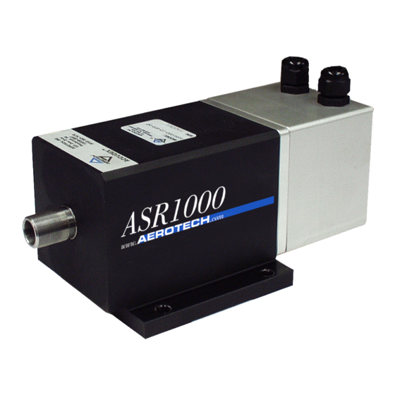
- Page 1 ASR1000 Rotary Stage Hardware Manual Revision: 1.00.00...
- Page 2 This manual contains proprietary information and may not be reproduced, disclosed, or used in whole or in part without the express written permission of Aerotech, Inc. Product names mentioned herein are used for identification purposes only and may be trademarks of their respective companies.
-
Page 3: Table Of Contents
ASR1000 Hardware Manual Table of Contents Table of Contents ASR1000 Rotary Stage Hardware Manual Table of Contents List of Figures List of Tables Safety Procedures and Warnings EU Declaration of Incorporation Chapter 1: Overview 1.1. Environmental Specifications 1.2. Accuracy and Temperature Effects 1.3. -
Page 4: List Of Figures
Table of Contents ASR1000 Hardware Manual List of Figures Figure 2-1: ASR1000 Dimensions Figure 2-2: ASR1000 Stage Showing Mounting Plate (Top View) Figure 2-3: ASR1000 Stage Without Mounting Plate (Bottom View) Figure 2-4: Load Capability Figure 3-1: Motor and Feedback Wiring (-CN1 Option) -
Page 5: List Of Tables
ASR1000 Hardware Manual Table of Contents List of Tables Table 1-1: Model Options Table 1-2: Environmental Specifications Table 1-3: ASR1000 Series Specifications Table 2-1: Stage to Mounting Surface Hardware Table 3-1: 4-Pin HPD Motor Connector Pinouts (-CN1 Option) Table 3-2: 4-Pin D Motor Mating Connector Table 3-3: 25-Pin D Motor Connector Pinouts (-CN2 Option) -
Page 6: Safety Procedures And Warnings
D A N G E R : This product contains potentially lethal voltages. To reduce the possibility of electrical shock, bodily injury, or death the following precautions must be followed. 1. Access to the ASR1000 and component parts must be restricted while connected to a power source. -
Page 7: Eu Declaration Of Incorporation
ASR1000 Hardware Manual Table of Contents EU Declaration of Incorporation Manufacturer: Aerotech, Inc. 101 Zeta Drive Pittsburgh, PA 15238-2811 herewith declares that the product: ASR1000 Stage is intended to be incorporated into machinery to constitute machinery covered by the Directive 2006/42/EC as amended;... - Page 8 Table of Contents ASR1000 Hardware Manual This page intentionally left blank. viii www.aerotech.com...
-
Page 9: Chapter 1: Overview
Overview Chapter 1: Overview N O T E : Aerotech continually improves its product offerings; listed options may be superseded at any time. All drawings and illustrations are for reference only and were complete and accurate as of this manual’s release. Refer to www.aerotech.com for the most up-to-date information. -
Page 10: Environmental Specifications
Extreme temperature changes could cause a decrease in performance or permanent damage to the stage. Aerotech stages are designed for and built in a 20°C (68°F) environment. Any deviation from standard operating temperature will affect stage accuracy. The severity of temperature effects on all stage specifications depends on many different environmental conditions, including how the stage is mounted. -
Page 11: Basic Specifications
Overview 1.3. Basic Specifications N O T E : Aerotech continually improves its product offerings; listed options may be superseded at any time. All drawings and illustrations are for reference only and were complete and accurate as of this manual’s release. Refer to www.aerotech.com for the most up-to-date information. - Page 12 Overview ASR1000 Hardware Manual This page intentionally left blank. Chapter 1 www.aerotech.com...
-
Page 13: Chapter 2: Installation
Installation Chapter 2: Installation W A R N I N G : ASR1000 installation must be in accordance to instructions provided by this manual and any accompanying documentation. Failure to follow these instructions could result in injury or damage to the equipment. -
Page 14: Dimensions
Installation ASR1000 Hardware Manual 2.2. Dimensions N O T E : All drawings and illustrations are for reference only and were complete and accurate as of this manual’s release. The most recent system drawings and schematics can be found on your software DVD or on www.aerotech.com. -
Page 15: Securing The Stage To The Mounting Surface
Installation 2.3. Securing the Stage to the Mounting Surface W A R N I N G : Do not attempt to manually move the ASR1000 if it is connected to a power source. W A R N I N G : Make sure that all moving parts are secure before moving the ASR1000. -
Page 16: Figure 2-2: Asr1000 Stage Showing Mounting Plate (Top View)
Installation ASR1000 Hardware Manual Figure 2-2: ASR1000 Stage Showing Mounting Plate (Top View) Figure 2-3: ASR1000 Stage Without Mounting Plate (Bottom View) Chapter 2 www.aerotech.com... -
Page 17: General Mechanical Setup
ASR1000 Hardware Manual Installation 2.4. General Mechanical Setup www.aerotech.com Chapter 2... -
Page 18: Load Capability
Installation ASR1000 Hardware Manual 2.5. Load Capability The ASR1000 is designed for tubular manufacturing applications. N O T E : Maximum loads are mutually exclusive. Figure 2-4: Load Capability Chapter 2 www.aerotech.com... -
Page 19: Chapter 3: Electrical Specifications And Installation
Aerotech motion control systems are adjusted at the factory for optimum performance. When the ASR1000 is part of a complete Aerotech motion control system, setup usually involves connecting the ASR1000 to the appropriate drive chassis with the cables provided. Labels on the system components usually indicate the appropriate connections. -
Page 20: Motor And Feedback Connectors
Stages equipped with standard motors and encoders come from the factory completely wired and assembled. N O T E : If using standard Aerotech motors and cables, motor and encoder connection adjustments are not required. The protective ground connection of the ASR1000 provides motor frame ground protection only. Additional grounding and safety precautions are required for applications requiring access to the stage while it is energized. - Page 21 ASR1000 Hardware Manual Operating Specifications Table 3-3: 25-Pin D Motor Connector Pinouts (-CN2 Option) Description Connector Motor Shield (EMI shield) Frame ground Frame ground Frame ground Motor Phase C Motor Phase B Motor Phase A Pins 3, 7, 10, 16, 19, and 23 have been removed.
- Page 22 Operating Specifications ASR1000 Hardware Manual Table 3-5: 25-Pin D Feedback Connector Pinouts Description Connector Signal shield connection Reserved +5 V power supply (the typical requirement is 250 mA). Reserved Reserved Marker-N Marker Reserved Reserved Reserved Reserved Reserved Reserved Cosine Cosine-N +5 V power supply...
-
Page 23: Motor And Feedback Wiring
ASR1000 Hardware Manual Operating Specifications 3.2. Motor and Feedback Wiring Shielded cables are required for the motor and feedback connections. Figure 3-1: Motor and Feedback Wiring (-CN1 Option) www.aerotech.com Chapter 3... -
Page 24: Figure 3-2: Motor And Feedback Wiring (-Cn2 Option)
Operating Specifications ASR1000 Hardware Manual Figure 3-2: Motor and Feedback Wiring (-CN2 Option) Chapter 3 www.aerotech.com... -
Page 25: Motor And Feedback Specifications
5. Torque constant and motor constant specified at stall 6. Maximum winding temperature is 130 °C 7. Ambient operating temperature range 0 °C - 25 °C; consult Aerotech for performance in elevated ambient temperatures 8. All Aerotech amplifiers are rated A ;... -
Page 26: Machine Direction
Operating Specifications ASR1000 Hardware Manual 3.4. Machine Direction Aerotech stages are configured to have positive and negative "machine" directions. The machine direction defines the phasing of the feedback and motor signals and is dictated by the stage wiring (refer to Section 3.5. -
Page 27: Motor And Feedback Phasing
ASR1000 Hardware Manual Operating Specifications 3.5. Motor and Feedback Phasing Motor phase voltage is measured relative to the virtual wye common point. Figure 3-4: Motor Phasing www.aerotech.com Chapter 3... -
Page 28: Figure 3-5: Analog Encoder Phasing Reference Diagram
Operating Specifications ASR1000 Hardware Manual Figure 3-5: Analog Encoder Phasing Reference Diagram Chapter 3 www.aerotech.com... -
Page 29: Chapter 4: Maintenance
4.1. Service and Inspection Schedule A frequent inspection and cleaning interval of the ASR1000 series stages is recommended until a trend develops for the application. The inspection and cleaning interval depends on application conditions such as duty cycle, speed, and environment. -
Page 30: Cleaning And Lubrication
ASR1000 Hardware Manual 4.2. Cleaning and Lubrication Before using a cleaning solvent on any part of the ASR1000, blow away small particles and dust with nitrogen or, less preferably, clean, dry, compressed air. Any metal surface on the stage can be cleaned with either acetone or isopropyl alcohol. Cleaning solvents, especially acetone, should not be used on any rubber components (o-rings and seals). -
Page 31: Troubleshooting
ASR1000 Hardware Manual Maintenance 4.3. Troubleshooting This section provides some information regarding typical problems. Table 4-1: Troubleshooting Symptom Possible Cause and Solution Stage will not move Controller trap or fault (refer to controller documentation). Encoder (sine and cosine) signal connections (refer to... - Page 32 Maintenance ASR1000 Hardware Manual This page intentionally left blank. Chapter 4 www.aerotech.com...
-
Page 33: Appendix A: Warranty And Field Service
Aerotech makes no warranty that its products are fit for the use or purpose to which they may be put by the buyer, whether or not such use or purpose has been disclosed to Aerotech in specifications or drawings previously or subsequently provided, or whether or not Aerotech’s... - Page 34 Aerotech's approval. On-site Warranty Repair If an Aerotech product cannot be made functional by telephone assistance or by sending and having the customer install replacement parts, and cannot be returned to the Aerotech service center for repair, and if Aerotech determines the problem could be warranty-related, then the following policy applies:...
-
Page 35: Appendix C: Revision History
ASR1000 Hardware Manual Revision History Appendix C: Revision History Revision General Information 1.00.00 New manual www.aerotech.com Appendix B... - Page 36 Revision History ASR1000 Hardware Manual This page intentionally left blank. Appendix B www.aerotech.com...
-
Page 37: Index
ASR1000 Hardware Manual Index Index overview 2010 part number performance (temperature) accuracy and temperature Protection Rating Altitude protective ground connection Ambient Temperature Securing the Stage to the Mounting Surface BM250 serial number service schedule cleaning solvent Shimming specifications Dimensions temperature... - Page 38 Index ASR1000 Hardware Manual This page intentionally left blank. Index www.aerotech.com...
Need help?
Do you have a question about the ASR1000 and is the answer not in the manual?
Questions and answers