Table of Contents
Advertisement
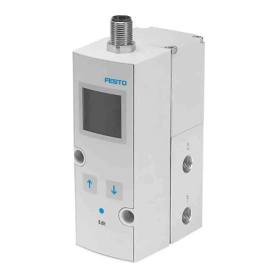
Poportional pressure regulator
VPPM−...C1 (LCD)
Operating instructions
Original: de
Note
Installation and commissioning may only be performed in accordance with these
operating instructions by technicians with appropriate qualifications.
Note
The product is suitable for use only for industrial purposes.
In residential areas, measures for radio interference suppression may be necess
ary.
1
Product description
1.1 Connections, mounting holes and control sections (in−line valve)
1
4
1
Electrical connecting plug M12
(8−pin)
2
Air connection (2), pressure output
3
Exhaust connection (3)
Fig. 1
1.2 Pneumatic connections (flanged valve)
1
3
1
Duct (2) air, pressure output
2
Duct (1) compressed air, supply port
Fig. 2
Festo AG & Co. KG
Postfach
D−73726 Esslingen
++49/711/347−0
www.festo.com
753 264
1007c
6
2
5
3
4
Through−holes for fastening
5
Compressed air connection (1),
supply port
6
Rating plate
3
Duct (3) exhaust
1.3 Display and control elements, display symbols
1
4
3
1
Display
2
DOWN button
Fig. 3
2
Application and function
The VPPM−...C1 has been designed for regulating a pressure proportional to a
specified setpoint value. A built−in pressure sensor records the pressure at the
working line and compares this value with the setpoint value. If the actual value
differs from the setpoint value, the regulating valve is actuated further until the
output pressure reaches the setpoint value.
Setpoint value
+W
−W
Setpoint value
Exhaust
3
1
Supply port
Fig. 4
3
Variants of the VPPM−...
Type code of the VPPM−...
1
VPPM − 6L − L − 1 − G18 − 0L6H −
2
4
Item
Properties
1
Nominal size [mm]
Valve type
2
Dynamic response class
3
Valve function
4
Pneumatic port
Flange/sub−base
ISO thread
NPT thread
5
Standard control range:
Lower pressure value
Upper pressure value
Alternative control ranges
Lower pressure value
Upper pressure value
2
6
Setpoint specification
Switching output
7
Accuracy
Operator unit
When an upper and lower pressure value are used, it is not possible to guarantee the overall
1)
accuracy of the VPPM−...C1.
Fig. 5
2
3
EDIT button
4
UP button
X
Pin 6
2
Pressure output
4
5
6
−
V1N
S1C1
3
Meaning
6, 8
F (flanged), L (in−line)
L (Low)
1 (3−way pressure regulator
normally closed)
F
G18 (1/8"), G14 (1/4")
N18 (NPT 1/8), N14 (NPT 1/4)
0L (0 bar)
2H (2 bar), 6H (6 bar), 10H (10 bar)
1)
:
...L(... = value between 0.1...10 bar)
e.g. 4L
...H (... = value between
0.1...10 bar) e.g. 9H
A4 (4 ... 20 mA), V1 (0 ... 10 V)
P (PNP), N (NPN)
... (2 %, standard), S1 (1 %)
... (LED), C1 (LCD)
7
Advertisement
Table of Contents

Subscribe to Our Youtube Channel
Related Manuals for Festo VPPM-C1 Series


Summary of Contents for Festo VPPM-C1 Series
- Page 1 1.3 Display and control elements, display symbols Poportional pressure regulator VPPM−...C1 (LCD) Festo AG & Co. KG Postfach D−73726 Esslingen ++49/711/347−0 www.festo.com Display EDIT button Operating instructions 753 264 DOWN button UP button 1007c Fig. 3 Application and function The VPPM−...C1 has been designed for regulating a pressure proportional to a Original: de specified setpoint value.
- Page 2 Fig. 13 Fig. 9 or stretched: · Use the pre−assembled plug socket with cable from Festo (for accessories, see www.festo.com\catalogue). You can then guarantee that the specified protec tion class IP 65 and EMC are fulfilled. · If a screened cable is used, earth the screening on the opposite end of the cable...
- Page 3 Note Note If the Y−connecting cable type NEBV−M12G8−KD−..−M12G5 is connected to CPX When the operating voltage is switched on, the VPPM−...C1 will automatically be I/O modules, the I/O modules will no longer be galvanically isolated. in the RUN mode (basic setting). If you are not sure whether the VPPM−...C1 is in the RUN mode, hold the EDIT button down for 3 s.
- Page 4 6.3 Symbols on the display of the VPPM−...C1 The SHOW mode shows the following settings and values: Settings for [Out]: Switching function [threshold value/window comparator/SP.O.] Switching point [SP] or [SP min] and [SP max] Hysteresis [HY] Switching characteristic [NO/NC] · Press the UP button again several times and check the current values and set tings of [Out].
- Page 5 Not in function (FORCE) 1) Depends on the version of the VPPM−...C1 2) Depends on the setting in the [SPEC] menu Fig. 21 EDIT mode...
- Page 6 6.5 Configuring the VPPM−...C1 Switching points (SP...) and hysteresis (Hy) with NC setting (normally closed Editing the pressure range and the arrangement of the setpoint value display contact) 1. In order to activate the EDIT mode, press the EDIT button. With threshold value comparator setting Only with active security locking −...
- Page 7 · Remove the VPPM−...C1 from the mounting surface/H−rail. Output pressure: 0 V or 4 mA creates an output pressure of 0 bar Fig. 30 Accessories For accessories, see www.festo.com\catalogue Select a suitable parameter set: Safety setting Recommended parameter sets VPPM−... Sizes 1/8"...
- Page 8 Fig. 38 Set value voltage or set value current not · Check controller · Check connection applied VPPM−... C1 defective Send the device to Festo for re pairs. Electrics data 2 bar type 6 bar type 10 bar type Flow rate too low Restriction of the flow cross section due to ·...
Need help?
Do you have a question about the VPPM-C1 Series and is the answer not in the manual?
Questions and answers