
Related Manuals for Festo VPPI D Series


Summary of Contents for Festo VPPI D Series
- Page 1 VPPI-...-D Proportional-pressure regulator Descrip- tion | Assembly, Installation, Operating, Parameterisation 8116344 8116344 2019-12 [8116346]...
- Page 2 Translation of the original instructions Festo — VPPI-...-D — 2019-12...
- Page 3 Commissioning......................11 Parameterisation......................11 9.1.1 Function of the Operating Buttons................12 9.1.2 Menu Levels......................12 9.1.3 Contents of the Menu....................13 Cleaning........................20 Malfunctions....................... 20 11.1 Diagnostics........................20 11.2 Fault Clearance......................22 Disassembly........................ 22 Disposal........................23 Technical Data......................23 Festo — VPPI-...-D — 2019-12...
-
Page 4: Applicable Documents
The specialized personnel must be familiar with the installation and operation of electrical and pneu- matic control systems. Additional Information – Accessories è www.festo.com/catalogue. Service Contact your regional Festo contact person if you have technical questions è www.festo.com. Festo — VPPI-...-D — 2019-12... -
Page 5: Product Overview
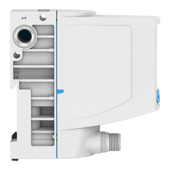
4 Working air port (2) 5 Exhaust air port (3) 6 Compressed air port (1) Fig. 1 Product Design Transport and Storage – Store the product in a dry, UV- and corrosion-protected environment. – Ensure short storage times. Festo — VPPI-...-D — 2019-12... - Page 6 2. Insert the O-ring into the duct (1) between 2 valves è Fig.2. Fig. 2 Insert O-ring 3. Connect the valves on the underside using socket head screws and square nuts. Tightening torque: 1.2 ± 0.2 Nm è Fig.3 Fig. 3 Fitting for valve underside Festo — VPPI-...-D — 2019-12...
- Page 7 For pressure zone separation, the plug screw can be left in duct (1) of the valve. Plug screws for duct (1) can also be ordered as accessories (VAME-P18-BP-G18-P5) è www.festo.com/catalogue. 1. Screw the plug screw into the duct (1) of the selected valve è Fig.5. Screw in the plug screw until it is flush with the surrounding surface.
- Page 8 Mounting via Underside of Valve Fig. 6 Mounting via underside of valve with M4 screws/M4 screws and square nuts 7.2.2 Mounting via Side Surface Fig. 7 Mounting via side surface with internal screws M4 / through screws M4 Festo — VPPI-...-D — 2019-12...
- Page 9 Mounting 7.2.3 Mounting of Linked Valves Fig. 8 Mounting of linked valves with lateral screws M4 7.2.4 Mounting on H-rail Fig. 9 Individual valve Festo — VPPI-...-D — 2019-12...
-
Page 10: Mechanical Installation
1. Attach the tubing to the connections: – Vacuum (3) – Working air (2) 2. Connect a compressed air supply to port (1) or mount a silencer to protect the valve from coarse dirt particles. Festo — VPPI-...-D — 2019-12... -
Page 11: Electrical Installation
1. Check operating conditions and critical limits è 14 Technical Data. 2. Switch on the power supply. 3. Switch on the compressed air supply. 4. Parameterise valve. Parameterisation The valve can be parameterised in the display menu using the 3 operating buttons. Festo — VPPI-...-D — 2019-12... - Page 12 Navigate within a menu level. Navigate to the Menu Item "Exit"with the Left or Right Pushbutton and Confirm with the Middle Pushbutton: – Navigate one menu level higher. 9.1.2 Menu Levels Fig. 11 Menu levels (excerpt) Festo — VPPI-...-D — 2019-12...
- Page 13 The set value is the time constant (tau) in milli- 75/125/250/500/ seconds. 750/1000/1500/ 2000 "Ramp-down-time" "Off"/X ms Setpoint jumps downwards are filtered with a low- pass filter. The set value is the time constant (tau) in 75/125/250/500/ milliseconds. 750/1000/1500/ 2000 Festo — VPPI-...-D — 2019-12...
- Page 14 Setpoint value (+): DI0 or least significant bit • Setpoint value (-): DI1 • Actual value output: DI2 or most significant bit The value 000 means 0 bar, the remaining 7 values can be set in "Input values". Festo — VPPI-...-D — 2019-12...
- Page 15 Appears only if "Input type" ="Digital" Delayed output of edge changes at the actual value output in order to filter short status changes (for example with setpoint value jumps). Shorter pulses than defined in "Output delay" are not out- put. Festo — VPPI-...-D — 2019-12...
- Page 16 "Reference run" "Start" Appears only if "Parameter set" = "Custom". "Tune pres incr" E.g. 5200 "Tuning pressure increase" appears only if "Para- meter set" = "Custom". Setting of the tuning parameter for pressure jumps upwards. Festo — VPPI-...-D — 2019-12...
- Page 17 This considerably reduces settling times for pressure jumps. The two required model parameters ("Tuning increase"/"Tuning decrease") can be determined automatically via hom- ing. The determined model parameters can also be adjusted manually afterwards. Free entry of these two model parameters without homing is also possible. Festo — VPPI-...-D — 2019-12...
- Page 18 Commissioning 1 Target pressure 3 Pressure in the working volume 2 Valve pressure at the working port Fig. 12 Pressure jump in standard regulator (basic representation) Festo — VPPI-...-D — 2019-12...
- Page 19 Application too fast (no bottleneck) – Extremely slow application (very large volume, very long tubing) In these cases, the parameter set "Custom" can be used by manually entering the parameters "Tune pres incr"/"Tune pres decr". Festo — VPPI-...-D — 2019-12...
- Page 20 Operating voltage 2. Clean the outside of the product with a soft cloth. Do not use aggressive cleaning agents. Malfunctions 11.1 Diagnostics The following table shows an overview of the error messages in the display. Festo — VPPI-...-D — 2019-12...
- Page 21 Input pressure p1 is too low. Maintain permissible maximum Air consumption at the working operating pressure port is too high. 14 Technical Data. è "Setpoint high" Analogue setpoint value is too Correct setpoint value. high. Tab. 10 Festo — VPPI-...-D — 2019-12...
-
Page 22: Fault Clearance
Tab. 11 Fault Clearance Disassembly 1. Switch off compressed air supply. 2. Specify setpoint value 0 bar. 3. Switch off operating voltage. 4. Remove electrical connecting cables. 5. Remove compressed air lines. 6. Dismantle the product. Festo — VPPI-...-D — 2019-12... -
Page 23: Technical Data
Lubricated operation not possible medium Climate class to EN60721 Nominal insert height 3000 m above sea level < Vibration resistance/shock resistance (as per IEC 60068) Note Explanation of the severity levels (SG) Tab. 14 Features of severity level (SL) è Festo — VPPI-...-D — 2019-12... - Page 24 Tab. 14 Features of severity level (SL) Pneumatic Characteristic Values Product type Input pressure at (1) Operating pressure at (1) [MPa] [bar] [MPa] [bar] VPPI -...- 1V0H -... 0 0.6 0 6 0 0.2 0 2 … … … … Festo — VPPI-...-D — 2019-12...
- Page 25 Working pressure (2) is exhausted to the pressure at the exhaust port (3). Tab. 16 Normal Position Cable Break Detection Valve variant Menu setting "Input Cable Break Detection min" VPPI-… -A4-… 2 mA Cable break detection inactive. < Festo — VPPI-...-D — 2019-12...
- Page 26 è Fig.14. Depending on the valve variant and the minimum input pressure, there may be a special response in this area è Tab. 18 Zero Point Suppression. Festo — VPPI-...-D — 2019-12...
- Page 27 Technical Data 1 Zero Point Suppression 3 Minimum input value 2 Minimum input value + 0.7% FS 4 Minimum pressure / vacuum Fig. 14 Zero Point Suppression Festo — VPPI-...-D — 2019-12...
- Page 28 Technical Data 1 Analogue setpoint value 3 Zero shutdown 2 Target pressure 4 Cable break Fig. 15 Valve variants for excess pressure and vacuum / excess pressure Festo — VPPI-...-D — 2019-12...
- Page 29 Operating voltage range 24 V DC 15 % ± Nominal current [mA] Current consumption [mA] 525 £ Permissible signal line 30 £ length Setpoint input Setpoint value input VPPI-… -V1-… [V DC] 0 10 … VPPI-… -A4-… [mA] 4 20 … Festo — VPPI-...-D — 2019-12...
- Page 30 Input resistance VPPI-… -V1 -... VPPI -...- A4 -... Actual value output Output current [mA] 25 £ Analogue output VPPI-… -V1-… [V DC] 0 10 … VPPI-… -A4-… [mA] 4 20 … Tab. 19 Electrical Characteristic Values Festo — VPPI-...-D — 2019-12...
- Page 32 Copyright: Festo SE & Co. KG Ruiter Straße 82 73734 Esslingen Germany Phone: +49 711 347-0 Internet: © 2020 all rights reserved to Festo SE & Co. KG www.festo.com...
Need help?
Do you have a question about the VPPI D Series and is the answer not in the manual?
Questions and answers