Chapters
Table of Contents

Related Manuals for Festo VPPM Series


Summary of Contents for Festo VPPM Series
- Page 1 Proportional Druckregelventil Proportional pressure regulator VPPM−... (de) Bedienungs− anleitung (en) Operating instructions nicht für Typ VPPM−...C1 not for type VPPM−...C1 741 073 0810b...
- Page 2 ..............Festo VPPM−... 0810b...
-
Page 3: Table Of Contents
..........Festo VPPM−... 0810b Deutsch... -
Page 4: Anschlüsse, Bedienteile Und Varianten
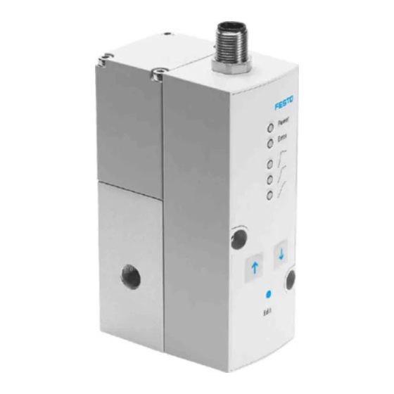
VPPM−...−DE/EN Anschlüsse, Bedienteile und Varianten Bedienteile und Anschlüsse des VPPM−... (Muffenventil) Stecker für elektrischen Anschluss (8−polig) Druckluftanschluss 1 (Druckeingang) LED Betriebs− und Statusanzeigen Arbeitsluftanschluss 2 (Druckausgang) DOWN−Taste Entlüftungsanschluss 3 EDIT−Taste Durchgangsbohrungen zur Befestigung UP−Taste Bild 1 Festo VPPM−... 0810b Deutsch... -
Page 5: Pneumatische Anschlüsse Des Vppm
VPPM−...−DE/EN Pneumatische Anschlüsse des VPPM−... (Flanschventil) Kanal Druckluft (Druckeingang) Kanal Entlüftung Kanal Arbeitsluft (Druckausgang) Bild 2 Festo VPPM−... 0810b Deutsch... -
Page 6: Varianten Des Vppm
...H (... = Wert zwischen 0 ... 10 bar, z.B. 8H) Sollwertvorgabe A4 (4 ... 20 mA) / V1 (0 ... 10 V) Schaltausgang P (PNP) / N (NPN; Standard) Gesamtgenauigkeit ... (2 %) / S1 (1 %) Bediengerät ... (LED) / C1 (LCD) Bild 3 Festo VPPM−... 0810b Deutsch... -
Page 7: Funktion Und Anwendung
Berufsgenossenschaft, des Technischen Überwachungsvereins, des VDE oder entsprechende nationale Bestimmungen. Entfernen Sie die Transportvorkehrungen wie Schutzwachs, Folien (Polyamid), Bild 6 Kappen (Polyethylen), Kartonagen. Die Verpackungen sind vorgesehen für eine Verwertung auf stofflicher Basis (Aus nahme: Ölpapier = Restmüll). Festo VPPM−... 0810b Deutsch... -
Page 8: Einbau
Achten Sie auf genügend Platz für den Kabelanschluss und die Schlauchan schlüsse. Dadurch wird ein Abknicken des Anschlusskabels vermieden. Platzieren Sie das VPPM−... möglichst nahe am Verbraucher. Dies führt zu besserer Regelgenauigkeit und kürzeren Ansprech zeiten. Bild 7 Festo VPPM−... 0810b Deutsch... - Page 9 Schrauben an das VPPM−... (Anzugsdrehmoment ca. 1,0 Nm): für x": M4 x 65 für ¼": M4 x 75 S Hängen Sie das VPPM−... in die Hutschiene. S Sichern Sie das VPPM−... mit den Sicherungsschrauben des Hutschienenadapters (Anziehdrehmoment 1,5 Nm). Bild 8 Festo VPPM−... 0810b Deutsch...
- Page 10 Ó Ó Ó Ó Ó Ó Ó Ó Ó Ó Ô Ô Ô Ô Ó Ó Ó Ó Ó Ó Ó Ó Befestigungsschrauben M4 Hutschienen−Klemmeinheit (Anziehdrehmoment siehe Bild 8) Hutschienenadapter Typ VAME−P1−T VPPM−... Hutschiene Bild 9 Festo VPPM−... 0810b Deutsch...
-
Page 11: Pneumatisch
Stellen Sie sicher, dass die Kabel quetsch−, knick− und dehnungsfrei verlegt sind: Verwenden Sie das vorkonfektionierte Bild 11 Steckdosenkabel von Festo (siehe Abschnitt 9 Zubehör"). Dadurch ist gewährleistet, dass die vorgegebene Schutzart IP65 und EMV erreicht wird. Festo VPPM−... 0810b Deutsch... - Page 12 Verkabeln Sie das VPPM−... gemäß eines der entsprechenden Anschlussbilder: Anschlussbilder VPPM−... Spannungsvariante (Typ VPPM−...−V1...) Stromvariante (Typ VPPM−...−A4...) 0...10 V 4...20 mA W− W− D1 ext in D2 ext in D1 ext in D2 ext in Bild 12 Festo VPPM−... 0810b Deutsch...
- Page 13 (RD) Digitaler Ausgang D3 PE Schirmgeflecht auf Gewinde 1) Bei Verwendung der Anschlussdose mit Kabel lt. Zubehör 2) Das Anziehdrehmoment beträgt max. 0,5 Nm 3) Die Hysterese des digitalen Komparatorausgangs D3 beträgt 0,5% FS Bild 13 Festo VPPM−... 0810b Deutsch...
- Page 14 Der digitale Schaltausgang D3 wird aktiv, sobald die Regelabweichung ˚ 0,5% FS beträgt und wird inaktiv, wenn die Regelabweichung > 1% FS überschreitet. Diagramm zur Schaltvariante PNP Sollwert obere Toleranzgrenze Istwert untere Toleranzgrenze Bild 14: P−Variante (PNP) Festo VPPM−... 0810b Deutsch...
- Page 15 VPPM−...−DE/EN Diagramm zur Schaltvariante NPN Sollwert obere Toleranzgrenze Istwert untere Toleranzgrenze Bild 15: N−Variante (NPN) Schaltbilder VPPM−... Schaltausgang +24 V +24 V Bild 16 Festo VPPM−... 0810b Deutsch...
-
Page 16: Inbetriebnahme
Das Regelverhalten des VPPM kann über die digitalen Eingänge D1 und D2 auch ferngesteuert eingestellt werden: Parameter Regelverhalten Eingang D1 Eingang D2 satz PIN 1 PIN 5 schnelles Regelverhalten universelles Regelverhalten (Werkseinstellung) präzises Regelverhalten 1 = 24 V DC / 0 = 0 V DC Bild 17 Festo VPPM−... 0810b Deutsch... - Page 17 0,1 bar 10 bar FS = Full scale (1 % FS = 0,1 V bzw. 0,16 mA / 100 % FS = 10 V bzw. 16 mA) 0 V bzw. 4 mA = 0 bar Bild 19 Festo VPPM−... 0810b Deutsch...
-
Page 18: Bedienung Und Betrieb
Schalten Sie zur äußeren Reinigung folgende Energiequellen ab: Betriebsspannung Druckluft Reinigen Sie bei Bedarf das VPPM−... von außen mit einem weichen Lappen. Die zulässigen Reinigungsmittel sind eine milde Seifenwasserlösung (max. +50 °C) oder alle werkstoffschonenden Medien. Festo VPPM−... 0810b Deutsch... -
Page 19: Ausbau
Trennen Sie die jeweiligen Anschlüsse vom VPPM−... Demontieren Sie das VPPM−... von der Befestigungsfläche/Hutschiene. Zubehör Bezeichnung Steckdosenkabel gerade SIM−M12−8GD−...−PU Steckdosenkabel gewinkelt NEBU−M12W8−...−N−LE8 Y−Anschlusskabel (zum Anschließen des VPPM−... an NEBV−M12G8−KD−...−M12G5 analoge Ein−/Ausgänge) Hutschienenbefestigung VAME−P1−T Winkel VAME−P1−A Anschlussblock VABM−P1−SF−G18−...−P3 Bild 21 Festo VPPM−... 0810b Deutsch... -
Page 20: Sicherheitseinstellung
Störungsbeseitigung Ursache Zustand der LED Anzeigen Power LED (grün) ERROR−LED (rot) Unterspannung bzw. leuchtet leuchtet Überspannung des Sollwertes Hardwarefehler leuchtet blinkt Überspannung (> 30 V) Interne Temperatur zuhoch Unterspannung (< 18 V) dunkel dunkel Bild 23 Festo VPPM−... 0810b Deutsch... - Page 21 P1 Manuelles Aus Auf den digitalen Eingängen An digitale Eingänge D1 und wählen der Para D1 und D2 liegt Spannung an D2 0 V DC anlegen metersätze über UP/DOWN−Tasten am VPPM−... nicht möglich Bild 24 Festo VPPM−... 0810b Deutsch...
-
Page 22: Technische Daten
0 ... +60 Mediumstemperatur [°C] +10 ... +50 Lagertemperatur [°C] 10 ... +70 El. Anschluss Steckkontakt M12x1, 8−polig Zul. Betriebsspannung [V DC] 21,6 ... 26,4 (zul. Restwelligkeit max. 10 %) Maximale elektrische Leistungsaufnahme 7 W (bei Dynamikklasse L) Festo VPPM−... 0810b Deutsch... - Page 23 5 g Beschleunigung bei 60 ... 150 Hz Schock Geprüft nach DIN/IEC 68/EN 60068 Teil 2−27; bei Wandmontage: ±30 g bei 11 ms Dauer; 5 Schocks je Richtung Werkstoffe Gehäuse AL−Knetlegierung Deckel PAXMD6−GF50/gr−P; PA6−GB20,GF10/gr−P Dichtungen Schmierung Silikonfrei Gewicht 400 g Bild 25 Festo VPPM−... 0810b Deutsch...
- Page 24 VPPM−...−DE/EN Durchflusskennlinien 2 bar Ventilvariante: Typ VPPM−6L−...−OL2H−... 6 bar Ventilvariante: Typ VPPM−6L−...−OL6H−... 10 bar Ventilvariante: Typ VPPM−6L−...−OL10H−... Bild 26 Festo VPPM−... 0810b Deutsch...
- Page 25 ........Festo VPPM−... 0810b English...
-
Page 26: Connections, Operating Elements And Variants
Plug for electrical connection (8−pin) Supply port 1 (pressure input) LED for operational and status displays Air port 2 (pressure output) DOWN button Valve exhaust port 3 EDIT button Through holes for fastening UP button Fig. 1 Festo VPPM−... 0810b English... -
Page 27: Pneumatic Connections Of The Vppm
VPPM−...−DE/EN Pneumatic connections of the VPPM−... (flanged valve) Compressed air channel (pressure input) Exhaust channel Air channel (pressure output) Fig. 2 Festo VPPM−... 0810b English... -
Page 28: Variants Of The Vppm
A4 (4 ... 20 mA) / V1 (0 ... 10 V) Switch output P (PNP) / N (NPN; Standard) Overall precision ... (2 %) / S1 (1 %) Operator unit ... (LED) / C1 (LCD) Fig. 3 Festo VPPM−... 0810b English... -
Page 29: Function And Application
(polyethylene), cardboard boxes. It is intended that the packaging be Fig. 6 recycled on the basis of its constituent materials (exception: oiled paper = other waste). Use the product in its original state. Unauthorized modification is not permitted. Festo VPPM−... 0810b English... -
Page 30: Fitting
This prevents kinks in the connecting cable. Place the VPPM−... as close to the con sumer as possible. This results in better control precision and shorter response times. Fig. 7 Festo VPPM−... 0810b English... - Page 31 (Tightening torque approx. 1.0 Nm): for x": M4 x 65 for ¼": M4 x 75 S Hang the VPPM−... onto the H−rail. S Secure the VPPM−... with the retaining screws of the H−rail adapter (tightening torque 1.5 Nm). Fig. 8 Festo VPPM−... 0810b English...
- Page 32 Ó Ó Ó Ó Ô Ô Ó Ó Ô Ô Ó Ó Ó Ó Ó Ó Ó Ó M4 mounting screws H−rail clamping unit (tightening torque, see Fig. 8) H−rail adapter type VAME−P1−T VPPM−... H−rail Fig. 9 Festo VPPM−... 0810b English...
-
Page 33: Pneumatic Installation
Make sure that the cable installation is neither squashed, bent nor stretched: Use the pre−assembled plug socket with cable from Festo (see chapter 9 Acces Fig. 11 sories"). This ensures that the specified protection class IP65 and EMC are ful filled. - Page 34 Wire the VPPM−... according to the appropriate connection diagrams: VPPM−... connection diagrams Voltage variant (type VPPM−...−V1...) Current variant (type VPPM−...−V4...) 0...10 V 4...20 mA W− W− D1 ext in D2 ext in D1 ext in D2 ext in Fig. 12 Festo VPPM−... 0810b English...
- Page 35 PE braided screen on thread Using the connection socket with cable as specified in the chapter Accessories" The max. tightening torque is 0.5 Nm. 3) The hysteresis of the digital comparator output D3 is 0.5% Fs. Fig. 13 Festo VPPM−... 0810b English...
- Page 36 ˚ 0.5% FS (full scale) and becomes inactive when the deviation from the target value exceeds > 1%FS. Diagram of switching variant PNP Target value Upper tolerance limit Actual value Lower tolerance limit Fig. 14: P−variant (PNP) Festo VPPM−... 0810b English...
- Page 37 VPPM−...−DE/EN Diagram of switching variant NPN Target value Upper tolerance limit Actual value Lower tolerance limit Fig. 15: N−variant (NPN) VPPM−... circuit diagrams Switch output +24 V +24 V Fig. 16 Festo VPPM−... 0810b English...
-
Page 38: Commissioning
D1 and D2. Parameter Control behaviour Input D1 Input D2 PIN 1 PIN 5 Fast control behaviour Universal control behaviour (factory setting) Precise control behaviour 1 = 24 V DC / 0 = 0 V DC Fig. 17 Festo VPPM−... 0810b English... - Page 39 0.1 bar 10 bar FS = Full scale (1 % FS = 0.1 V or 0.16 mA / 100 % FS = 10 V or 16 mA) 0 V or 4 mA = 0 bar Fig. 19 Festo VPPM−... 0810b English...
-
Page 40: Operation
If the VPPM−... is dirty, clean the exterior with a soft cloth. The approved cleaning agent is a mild soap water solution (max. +50 °C) or all media that are non−abrasive. Festo VPPM−... 0810b English... -
Page 41: Dismantling
Remove the VPPM−... from the mounting surface/H−rail. Accessories Designation Type Plug socket with cable, straight SIM−M12−8GD−...−PU Plug socket with cable, angled NEBU−M12W8−...−N−LE8 Y−cable (to connect the VPPM−... to analogue NEBV−M12G8−KD−...−M12G5 inputs/outputs) H−rail mounting VAME−P1−T Bracket VAME−P1−A Sub−base VABM−P1−SF−G18−...−P3 Fig. 21 Festo VPPM−... 0810b English... -
Page 42: Safety Setting
Power LED (green) ERROR LED (red) Undervoltage or overvoltage Lights up Lights up of the setpoint value Hardware fault Lights up Flashing Overvoltage (> 30 V) Internal temperature too high Undervoltage (< 18 V) Fig. 23 Festo VPPM−... 0810b English... - Page 43 24 VDC power supply. No setpoint voltage or setpoint Check controller, check current. connection. VPPM−... defective. Send in the device to the Festo repair service. Flow rate too low Restricted cross section of flow Use connection alternatives. due to connection technology (swivel fittings).
-
Page 44: Technical Specifications
Storage temperature [°C] 10 ... +70 Electrical connection Crimp connector M12x1, 8−pin Permissible operating [V DC] 21.6 ... 26.4 V DC (permissible residual ripple voltage max.: 10 %) Maximum electrical power 7W (with dynamic class L) consumption Festo VPPM−... 0810b English... - Page 45 DIN/IEC 68/EN 60068 parts 2−27; for wall mounting: ±30 g at 11 ms duration; 5 shocks per direction Materials Housing Al wrought alloy Cover PAXMD6−GF50/gr−P; PA6−GB20,GF10/gr−P Seals Lubrication Silicone−free Weight 400 g Fig. 25 Festo VPPM−... 0810b English...
- Page 46 VPPM−...−DE/EN Characteristic curves for flow rate 2 bar valve variant: type VPPM−6L−...−OL2H−... 6 bar valve variant: type VPPM−6L−...−OL6H−... 10 bar valve variant: type VPPM−6L−...−OL10H−... Fig. 26 Festo VPPM−... 0810b English...
- Page 47 VPPM−...−DE/EN Festo VPPM−... 0810b...
- Page 48 VPPM−...−DE/EN Copyright: Copyright: Festo AG & Co. KG, Festo AG & Co. KG, Postfach D−73726 Esslingen D−73726 Esslingen Phone: Weitergabe sowie Vervielfältigung dieses Dokuments, +49 / 711 / 347−0 Verwertung und Mitteilung seines Inhalts sind verboten, soweit nicht ausdrücklich gestattet. Zuwiderhandlungen Fax: verpflichten zu Schadenersatz.
Need help?
Do you have a question about the VPPM Series and is the answer not in the manual?
Questions and answers