
Related Manuals for Stryker Gynnie


Summary of Contents for Stryker Gynnie
- Page 1 G G y y n n n n i i e e ® ® O O B B / / G G Y Y N N S S t t r r e e t t c c h h e e r r M M a a i i n n t t e e n n a a n n c c e e M M a a n n u u a a l l 1061 1061-009-002 Rev A.0...
- Page 3 Operating instructions/Consult instructions for use General warning Caution No pushing Do not store the oxygen bottle Catalogue number Serial number For US Patents see www.stryker.com/patents CE mark Authorized representative in the European Community European medical device Manufacturer Safe working load Lubricate Type B applied part 1061-009-002 Rev A.0...
-
Page 5: Table Of Contents
T T a a b b l l e e o o f f C C o o n n t t e e n n t t s s Warning/Caution/Note Definition ..........................3 Summary of safety precautions ..........................3 Introduction ................................4 Product description ..............................4 Indications for use..............................4 Expected service life ...............................4... - Page 6 Litter assembly ................................41 Foot section assembly ............................45 Foot support pivot assembly - 1061-050-030 ......................48 Foot support assembly, right - 1061-050-010 ......................50 Foot support assembly, left - 1061-050-011 ......................52 Siderail to litter assembly ............................54 Seat/Fowler backrest assembly - 1061-131-100 ....................56 Pneumatic Fowler assembly - 1210-031-120 ......................57 Head end steering handles - 1711-151-000 ......................58...
- Page 7 W W a a r r n n i i n n g g / / C C a a u u t t i i o o n n / / N N o o t t e e D D e e f f i i n n i i t t i i o o n n The words W W A A R R N N I I N N G G , C C A A U U T T I I O O N N , and N N O O T T E E carry special meanings and should be carefully reviewed.
-
Page 8: Expected Service Life
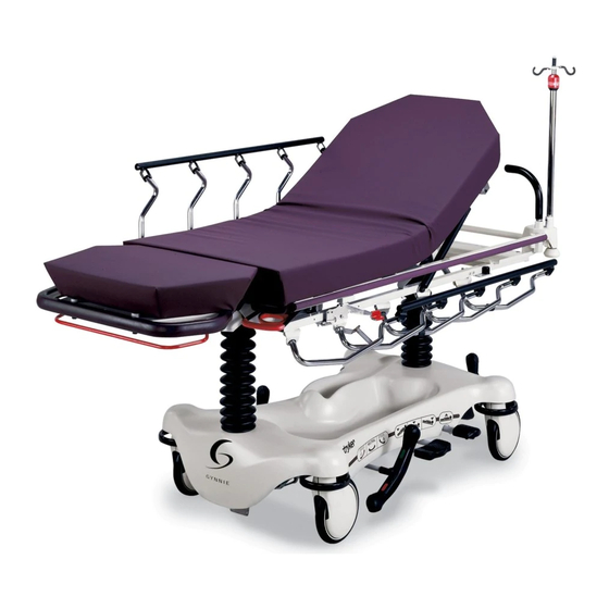
P P r r o o d d u u c c t t d d e e s s c c r r i i p p t t i i o o n n The Stryker Model 1061 G G y y n n n n i i e e ® ® OB/GYN stretcher is a wheeled stretcher consisting of a platform mounted on a wheeled frame to transport patients in a horizontal position while providing a platform for the clinical treatment or examination of patients within the interior of a healthcare facility. -
Page 9: Specifications
68 in. 172.7 cm Stryker reserves the right to change specifications without notice. O O p p e e r r a a t t i i o o n n S S t t o o r r a a g g e e a a n n d d t t r r a a n n s s p p o o r r t t a a t t i i o o n n E E n n v v i i r r o o n n m m e e n n t t a a l l c c o o n n d d i i t t i i o o n n s s 100 °F... - Page 10 N N o o t t e e - - The user and/or the patient should report any serious product-related incident to both the manufacturer and the Competent authority of the European Member State where the user and/or patient is established. To view your operations or maintenance manual online, see https://techweb.stryker.com/. 1061-009-002 Rev A.0...
- Page 11 Have the serial number (A) of your Stryker product available when calling Stryker Customer Service or Technical Support. Include the serial number in all written communication. S S e e r r i i a a l l n n u u m m b b e e r r l l o o c c a a t t i i o o n n F F i i g g u u r r e e 1 1 –...
-
Page 12: Preventive Maintenance
Remove product from service before you perform the preventive maintenance inspection. Check all items listed during annual preventive maintenance for all Stryker Medical products. You may need to perform preventive maintenance checks more often based on your level of product usage. Service only by qualified personnel. -
Page 13: Service
S S e e r r v v i i c c e e C C a a s s t t e e r r a a s s s s e e m m b b l l y y r r e e p p l l a a c c e e m m e e n n t t T T o o o o l l s s r r e e q q u u i i r r e e d d : : •... - Page 14 P P r r o o c c e e d d u u r r e e : : 1. Insert the large slotted screwdriver into the cut-out inside the wheel cover and into the space between the double prongs.
-
Page 15: Caster Assembly Replacement
F F i i g g u u r r e e 3 3 – – R R e e p p l l a a c c i i n n g g t t h h e e b b r r a a k k e e c c a a m m B B r r a a k k e e r r i i n n g g r r e e p p l l a a c c e e m m e e n n t t T T o o o o l l s s r r e e q q u u i i r r e e d d : : •... -
Page 16: Brake Adjustment
12. Reverse steps to install the supplied brake ring, caster, and wheel. 13. Apply and release the brakes to make sure that they work. Adjust as necessary (see Brake adjustment (page 12)). 14. Remove the bungee cords and lower the base hood. 15. - Page 17 F F i i g g u u r r e e 5 5 – – B B r r a a k k e e a a d d j j u u s s t t m m e e n n t t B B a a s s e e s s i i d d e e c c o o n n t t r r o o l l p p e e d d a a l l l l i i n n k k a a g g e e a a d d j j u u s s t t m m e e n n t t T T o o o o l l s s r r e e q q u u i i r r e e d d : : •...
- Page 18 • 5/32” hex wrench • (2) 9/16” box end wrench • 3/8” box end wrench • 3/16” punch • 1/4” punch • Pliers • Hammer • Floor jack • Bungee cords P P r r o o c c e e d d u u r r e e : : 1.
- Page 19 P P r r o o c c e e d d u u r r e e : : 1. Apply the brake. Push on the product to make sure that the brakes work. 2. Raise the litter to the highest position. 3.
- Page 20 • Spring compression tool • 1/2” socket • 1/2” wrench • 3” extension P P r r o o c c e e d d u u r r e e : : 1. Apply the brakes. Push on the product to make sure that the brakes work. 2.
-
Page 21: Base Side Control Pedal Linkage Adjustment
10. Check the fill level of the hydraulic fluid (fluid should be visible at the bottom of the fill hole). If necessary, add M M o o b b i i l l Aero HFA hydraulic fluid (Stryker pn 2020-070-245) until fluid is visible at the bottom of the fill hole. - Page 22 3. Locate the adjustable descent valve on the base of the jack. Turn the silver locking ring counterclockwise to loosen the ring. 4. To decrease the descent rate, turn the blue knob counterclockwise. 5. To increase the descent rate, turn the blue knob clockwise. 6.
- Page 23 F F i i g g u u r r e e 6 6 – – P P o o p p p p e e t t v v a a l l v v e e r r e e p p l l a a c c e e m m e e n n t t 14.
- Page 24 4. Using a 3/8” open end wrench, remove the square head set screws from both the head end and foot end jack support tubes. 5. Using a 3/8” open end wrench, remove the bolt in the litter support tube above the black bellows on both ends of the product.
- Page 25 10. Install the supplied P.C. valve (M). Moisten the O-ring seal (B) with hydraulic fluid to make sure that the O-ring seals tight. 11. Tighten the valve manually, and then use a 13/16” open end wrench to tighten an additional 1/8 to 1/4 turn. N N o o t t e e - - Do not overtighten or damage to the O-ring may occur.
- Page 26 F F i i g g u u r r e e 7 7 – – B B a a s s e e l l u u b b r r i i c c a a t t i i o o n n P P n n e e u u m m a a t t i i c c F F o o w w l l e e r r b b a a c c k k r r e e s s t t a a d d j j u u s s t t m m e e n n t t T T o o o o l l s s r r e e q q u u i i r r e e d d : : •...
-
Page 27: Foot Support Replacement
F F o o o o t t s s u u p p p p o o r r t t r r e e p p l l a a c c e e m m e e n n t t T T o o o o l l s s r r e e q q u u i i r r e e d d : : •... - Page 28 P P r r o o c c e e d d u u r r e e : : 1. Remove the foot support pivot assembly (see Foot support pivot assembly removal and replacement (page 23)). 2. Insert the extension tube through the slide opening of the pivot assembly. 3.
- Page 29 S S t t r r e e t t c c h h e e r r a a s s s s e e m m b b l l y y 1061-026-000 Rev AA (Reference only) I I t t e e m m N N u u m m b b e e r r N N a a m m e e Q Q u u a a n n t t i i t t y y...
- Page 30 I I t t e e m m N N u u m m b b e e r r N N a a m m e e Q Q u u a a n n t t i i t t y y 1060-030-010 Litter assembly (page 41) 1061-031-010...
- Page 31 S S t t a a n n d d a a r r d d c c a a s s t t e e r r a a s s s s e e m m b b l l y y 0715-002-020 Rev A (Reference only) I I t t e e m m N N u u m m b b e e r r...
-
Page 32: Standard Caster Assembly
B B a a s s e e a a s s s s e e m m b b l l y y w w i i t t h h f f i i f f t t h h w w h h e e e e l l o o p p t t i i o o n n 1010-260-010 Rev H (Reference only) I I t t e e m m N N u u m m b b e e r r... - Page 33 F F i i f f t t h h w w h h e e e e l l p p i i v v o o t t r r o o d d a a s s s s e e m m b b l l y y 1210-201-002 Rev A (Reference only) I I t t e e m m N N u u m m b b e e r r...
- Page 34 F F i i f f t t h h w w h h e e e e l l a a r r m m a a s s s s e e m m b b l l y y - - 0 0 7 7 1 1 5 5 - - 2 2 0 0 1 1 - - 1 1 2 2 5 5 Rev A (Reference only) I I t t e e m m N N u u m m b b e e r r...
- Page 35 B B a a s s e e a a s s s s e e m m b b l l y y 1061-001-010 Rev R (Reference only) Torque item H to 80 ± 90 ft-lb Torque item H to 80 ±...
- Page 36 1061-009-002 Rev A.0...
- Page 37 I I t t e e m m N N u u m m b b e e r r N N a a m m e e Q Q u u a a n n t t i i t t y y 0042-020-000 Collar 0715-001-011...
- Page 38 I I t t e e m m N N u u m m b b e e r r N N a a m m e e Q Q u u a a n n t t i i t t y y 0016-118-000 Lock nut 0016-035-000...
- Page 39 B B r r a a k k e e c c a a m m a a s s s s e e m m b b l l y y 0715-201-213 Rev B (Reference only) I I t t e e m m N N u u m m b b e e r r N N a a m m e e Q Q u u a a n n t t i i t t y y...
- Page 40 U U n n i i - - l l o o w w e e r r i i n n g g p p e e d d a a l l a a s s s s e e m m b b l l y y 1061-500-000 Rev A (Reference only) I I t t e e m m N N u u m m b b e e r r...
-
Page 41: Base Assembly
C C o o n n s s t t a a n n t t f f l l o o w w j j a a c c k k a a s s s s e e m m b b l l y y 1231-070-210 Rev C (Reference only) I I t t e e m m N N u u m m b b e e r r... - Page 42 I I t t e e m m N N u u m m b b e e r r N N a a m m e e Q Q u u a a n n t t i i t t y y 0045-904-000 O-ring 0045-978-000...
- Page 43 C C o o n n s s t t a a n n t t f f l l o o w w j j a a c c k k b b a a s s e e a a s s s s e e m m b b l l y y 5050-370-100 Rev C (Reference only) I I t t e e m m N N u u m m b b e e r r...
- Page 44 Bellows, head end 1210-201-335 Brake, red 1210-201-336 Steer, green 0946-201-060 Stryker logo 1061-201-060 Stryker logo, large 1061-700-123 Label, head end brake/steer control 1061-200-002 G G y y n n n n i i e e label 1061-700-221 Side control, right 1061-700-222...
- Page 45 L L i i t t t t e e r r a a s s s s e e m m b b l l y y 1061-030-010 Rev G (Reference only) 1061-009-002 Rev A.0...
- Page 46 1061-009-002 Rev A.0...
-
Page 47: Litter Assembly
I I t t e e m m N N u u m m b b e e r r N N a a m m e e Q Q u u a a n n t t i i t t y y 0037-010-000 Hole plug 0926-400-142... - Page 48 I I t t e e m m N N u u m m b b e e r r N N a a m m e e Q Q u u a a n n t t i i t t y y 1061-700-025 Siderail bumper 1211-030-018...
- Page 49 F F o o o o t t s s e e c c t t i i o o n n a a s s s s e e m m b b l l y y 1061-040-010 Rev K (Reference only) Torque item S to 9 ±...
- Page 50 I I t t e e m m N N u u m m b b e e r r N N a a m m e e Q Q u u a a n n t t i i t t y y 0721-040-026 Footboard receptacle 0946-001-155...
- Page 51 I I t t e e m m N N u u m m b b e e r r N N a a m m e e Q Q u u a a n n t t i i t t y y 0028-023-000 External snap ring 0038-355-000...
- Page 52 F F o o o o t t s s u u p p p p o o r r t t p p i i v v o o t t a a s s s s e e m m b b l l y y - - 1 1 0 0 6 6 1 1 - - 0 0 5 5 0 0 - - 0 0 3 3 0 0 Rev G (Reference only) I I t t e e m m N N u u m m b b e e r r...
- Page 53 I I t t e e m m N N u u m m b b e e r r N N a a m m e e Q Q u u a a n n t t i i t t y y 0004-442-000 Button head Torx screw 0011-180-000...
- Page 54 F F o o o o t t s s u u p p p p o o r r t t a a s s s s e e m m b b l l y y , , r r i i g g h h t t - - 1 1 0 0 6 6 1 1 - - 0 0 5 5 0 0 - - 0 0 1 1 0 0 Rev E (Reference only) I I t t e e m m N N u u m m b b e e r r...
- Page 55 I I t t e e m m N N u u m m b b e e r r N N a a m m e e Q Q u u a a n n t t i i t t y y 1061-050-042 Molded cup assembly 1061-050-037...
- Page 56 F F o o o o t t s s u u p p p p o o r r t t a a s s s s e e m m b b l l y y , , l l e e f f t t - - 1 1 0 0 6 6 1 1 - - 0 0 5 5 0 0 - - 0 0 1 1 1 1 Rev E (Reference only) I I t t e e m m N N u u m m b b e e r r...
- Page 57 I I t t e e m m N N u u m m b b e e r r N N a a m m e e Q Q u u a a n n t t i i t t y y 0038-454-000 Compression spring 0004-442-000...
- Page 58 S S i i d d e e r r a a i i l l t t o o l l i i t t t t e e r r a a s s s s e e m m b b l l y y 1061-120-010 Rev H (Reference only) I I t t e e m m N N u u m m b b e e r r...
- Page 59 I I t t e e m m N N u u m m b b e e r r N N a a m m e e Q Q u u a a n n t t i i t t y y 1001-226-047 Latch pivot, left 1001-226-116...
- Page 60 S S e e a a t t / / F F o o w w l l e e r r b b a a c c k k r r e e s s t t a a s s s s e e m m b b l l y y - - 1 1 0 0 6 6 1 1 - - 1 1 3 3 1 1 - - 1 1 0 0 0 0 Rev M (Reference only) I I t t e e m m N N u u m m b b e e r r...
- Page 61 P P n n e e u u m m a a t t i i c c F F o o w w l l e e r r a a s s s s e e m m b b l l y y - - 1 1 2 2 1 1 0 0 - - 0 0 3 3 1 1 - - 1 1 2 2 0 0 Rev F (Reference only) I I t t e e m m N N u u m m b b e e r r...
-
Page 62: Push Handle Assembly
H H e e a a d d e e n n d d s s t t e e e e r r i i n n g g h h a a n n d d l l e e s s - - 1 1 7 7 1 1 1 1 - - 1 1 5 5 1 1 - - 0 0 0 0 0 0 Rev B (Reference only) I I t t e e m m N N u u m m b b e e r r... - Page 63 P P u u s s h h h h a a n n d d l l e e a a s s s s e e m m b b l l y y 1211-351-010 Rev A (Reference only) I I t t e e m m N N u u m m b b e e r r N N a a m m e e...
- Page 64 I I V V p p o o l l e e , , r r e e m m o o v v a a b b l l e e - - 0 0 3 3 9 9 0 0 - - 0 0 2 2 5 5 - - 0 0 1 1 0 0 0390-025-000 Rev L (Reference only) I I t t e e m m N N u u m m b b e e r r...
- Page 65 T T w w o o - - s s t t a a g g e e I I V V p p o o l l e e a a s s s s e e m m b b l l y y - - 1 1 0 0 6 6 1 1 - - 1 1 1 1 0 0 - - 0 0 0 0 0 0 Rev B (Reference only) I I t t e e m m N N u u m m b b e e r r...
- Page 66 T T h h r r e e e e - - s s t t a a g g e e I I V V p p o o l l e e a a s s s s e e m m b b l l y y - - 1 1 0 0 6 6 1 1 - - 1 1 1 1 0 0 - - 0 0 0 0 1 1 Rev B (Reference only) I I t t e e m m N N u u m m b b e e r r...
- Page 67 U U p p r r i i g g h h t t o o x x y y g g e e n n b b o o t t t t l l e e h h o o l l d d e e r r a a s s s s e e m m b b l l y y - - 1 1 0 0 2 2 0 0 - - 1 1 3 3 0 0 - - 0 0 0 0 0 0 Rev A (Reference only) I I t t e e m m N N u u m m b b e e r r...
- Page 68 W W a a s s t t e e b b a a s s i i n n h h o o l l d d e e r r a a s s s s e e m m b b l l y y - - 1 1 0 0 6 6 1 1 - - 7 7 0 0 0 0 - - 0 0 0 0 1 1 1061-120-000 Rev C (Reference only) 0005-033-000 1061-030-010...
- Page 69 H H o o o o p p a a s s s s e e m m b b l l y y - - 1 1 0 0 6 6 1 1 - - 1 1 2 2 0 0 - - 0 0 3 3 2 2 Rev B (Reference only) I I t t e e m m N N u u m m b b e e r r...
-
Page 70: Calf Support Mount Assembly
C C a a l l f f s s u u p p p p o o r r t t m m o o u u n n t t i i n n g g b b r r a a c c k k e e t t s s - - 1 1 0 0 6 6 1 1 - - 1 1 3 3 0 0 - - 0 0 0 0 0 0 Rev A (Reference only) I I t t e e m m N N u u m m b b e e r r... - Page 71 C C a a l l f f s s u u p p p p o o r r t t m m o o u u n n t t a a s s s s e e m m b b l l y y 1061-130-001 Rev A (Reference only) I I t t e e m m N N u u m m b b e e r r...
-
Page 72: Free Standing Calf Rest Assembly
F F r r e e e e s s t t a a n n d d i i n n g g c c a a l l f f r r e e s s t t - - 1 1 0 0 6 6 1 1 - - 0 0 4 4 0 0 - - 0 0 3 3 6 6 Rev A (Reference only) I I t t e e m m N N u u m m b b e e r r... - Page 73 F F r r e e e e s s t t a a n n d d i i n n g g c c a a l l f f r r e e s s t t a a s s s s e e m m b b l l y y 1061-040-035 Rev D (Reference only) I I t t e e m m N N u u m m b b e e r r...
- Page 74 S S e e r r v v i i n n g g t t r r a a y y - - 0 0 7 7 8 8 5 5 - - 0 0 4 4 5 5 - - 7 7 0 0 0 0 Rev C (Reference only) I I t t e e m m N N u u m m b b e e r r...
- Page 75 O O x x y y g g e e n n b b o o t t t t l l e e r r e e t t a a i i n n e e r r a a s s s s e e m m b b l l y y - - 1 1 0 0 4 4 0 0 - - 0 0 1 1 0 0 - - 0 0 9 9 0 0 1040-010-095 Rev B (Reference only) I I t t e e m m N N u u m m b b e e r r...
- Page 76 M M a a t t t t r r e e s s s s e e s s a a n n d d s s i i d d e e r r a a i i l l p p a a d d s s (Reference only) Foot pad 1061-426-075...
- Page 77 Siderail pad set 1001-052-000 1061-009-002 Rev A.0...
- Page 78 A A n n k k l l e e r r e e s s t t r r a a i i n n t t s s t t r r a a p p - - 0 0 9 9 4 4 6 6 - - 0 0 4 4 3 3 - - 0 0 0 0 1 1 Rev G (Reference only) I I t t e e m m N N u u m m b b e e r r...
- Page 79 W W r r i i s s t t r r e e s s t t r r a a i i n n t t s s t t r r a a p p - - 0 0 9 9 4 4 6 6 - - 0 0 4 4 4 4 - - 0 0 0 0 0 0 Rev C (Reference only) N N u u m m b b e e r r N N a a m m e e...
- Page 80 B B o o d d y y r r e e s s t t r r a a i i n n t t s s t t r r a a p p - - 0 0 3 3 9 9 0 0 - - 0 0 1 1 9 9 - - 0 0 0 0 0 0 Rev E (Reference only) N N u u m m b b e e r r N N a a m m e e...
- Page 81 C C h h e e s s t t r r e e s s t t r r a a i i n n t t s s t t r r a a p p - - 1 1 0 0 1 1 0 0 - - 0 0 5 5 8 8 - - 0 0 0 0 0 0 Rev F (Reference only) N N u u m m b b e e r r N N a a m m e e...
- Page 82 F F u u l l l l r r e e s s t t r r a a i i n n t t s s t t r r a a p p p p a a c c k k a a g g e e - - 1 1 0 0 1 1 0 0 - - 0 0 7 7 7 7 - - 0 0 0 0 0 0 Rev C (Reference only) N N u u m m b b e e r r N N a a m m e e...
- Page 84 Stryker Medical 3800 E. Centre Avenue Portage, MI 49002 1061-009-002 Rev A.0 2019/09 WCR: AA.10...
Need help?
Do you have a question about the Gynnie and is the answer not in the manual?
Questions and answers